Download presentation
Presentation is loading. Please wait.

1
© 2008, Renesas Technology America, Inc., All Rights Reserved 1 Module Introduction Purpose This training module provides an overview of the peripherals in H8S series microcontrollers that you can use to transfer data without interrupting the CPU. Objective Understand the design, features, operation, and application of the Data Transfer Controller (DTC) and DMA Controller (DMAC). Content 23 pages 4 questions Learning Time 45 minutes
 and DMA Controller (DMAC). Content 23 pages 4 questions Learning Time 45 minutes.")
2
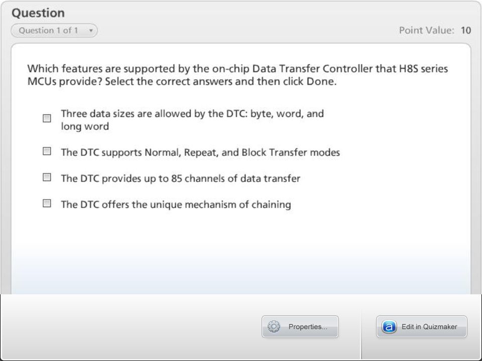
© 2008, Renesas Technology America, Inc., All Rights Reserved 2 DTC Basics Uses up to 1KB of on-chip RAM and provides up to 85 channels for data transfer Transfers data between memory and I/Os without interrupting the CPU

3
© 2008, Renesas Technology America, Inc., All Rights Reserved 3 DTC Features Up to 85 channels can be used Transfer is possible over any number of channels. Transfer information is stored in RAM. One activation source can trigger a number of data transfers (Chain Transfer). Multiple transfer modes Normal, Repeat, and Block Transfer modes available Option to select incrementing, decrementing, or fixed source/destination Direct specification of 16MB address space possible Transfer can be set in byte or word units Interrupt or software activation possible Can be halted by setting Module Standby mode
. Multiple transfer modes Normal, Repeat, and Block Transfer modes available Option to select incrementing, decrementing, or fixed source/destination Direct specification of 16MB address space possible Transfer can be set in byte or word units Interrupt or software activation possible Can be halted by setting Module Standby mode.")
4
© 2008, Renesas Technology America, Inc., All Rights Reserved 4 DTC Implementation

5
© 2008, Renesas Technology America, Inc., All Rights Reserved 5 DTC Registers in On-chip RAM

6
© 2008, Renesas Technology America, Inc., All Rights Reserved 6 DTC Operation 0xec00 CPU Address 0x400 Trigger Vector 0 Read Vector DTC Register Information CPU Address 0xffec00 0x4ff 0xffefff Read Register Information Transfer Occurs according to register information DTC updates register information XFER DONE

7
© 2008, Renesas Technology America, Inc., All Rights Reserved 7 Termination of DTC Transfers CHNE =1? Count = 0 Or DISEL = 1? Yes END Clear Activation Flag Clear DTCER Interrupt Exception Handling No “Termination”

8
© 2008, Renesas Technology America, Inc., All Rights Reserved 8 DTC Operating Modes Normal mode One transfer request transfers 1 byte or 1 word. Memory addresses are incremented or decremented by 1 or 2. Up to 65,536 transfers are possible. Repeat mode One transfer request transfers 1 byte or 1 word. Memory addresses are incremented or decremented by 1 or 2. After the specified number of transfers (1 to 256), the initial state resumes and operation continues. Block Transfer mode One transfer request transfers a data block of the specified size. Block size is from 1 to 256 bytes or words. Up to 65,536 transfers are possible. A block area can be designated at either the source or destination.
, the initial state resumes and operation continues. Block Transfer mode One transfer request transfers a data block of the specified size. Block size is from 1 to 256 bytes or words. Up to 65,536 transfers are possible. A block area can be designated at either the source or destination..")
9
© 2008, Renesas Technology America, Inc., All Rights Reserved 9 Chained Transfer Mode (SAR0) (SAR1) (DAR0) (DAR1) Transfer 0 Register Information Transfer 1 Register Information RAM
 (SAR1) (DAR0) (DAR1) Transfer 0 Register Information Transfer 1 Register Information RAM")
10
© 2008, Renesas Technology America, Inc., All Rights Reserved 10 DTC Offloads the CPU DTC-based Transfers CPU Tasks DTC register = HEADER Clean-up interrupt (Header end) DTC register = DATA Clean-up interrupt (DATA end) DTC register = TAIL Clean-up interrupt (TAIL end) Post processing CPU Totals (using DTC) 3 interrupts (context switch) 6 word writes (HEADER, DATA and TAIL register settings) [Number of CPU cycles = 30, minimum: (3 x 6) + (6 x 2) ] CPU-based Transfers CPU Tasks 3 HEADER interrupts 256 DATA interrupts 4 TAIL interrupts Post processing CPU Totals (DTC not used) 263 interrupts (context switch) 263-byte write for data Uncounted writes for stack operations (at least 263x2 for PC, CCR) [Number of CPU cycles = 1578, minimum: 263 x 6 ]
![© 2008, Renesas Technology America, Inc., All Rights Reserved 10 DTC Offloads the CPU DTC-based Transfers CPU Tasks DTC register = HEADER Clean-up interrupt (Header end) DTC register = DATA Clean-up interrupt (DATA end) DTC register = TAIL Clean-up interrupt (TAIL end) Post processing CPU Totals (using DTC) 3 interrupts (context switch) 6 word writes (HEADER, DATA and TAIL register settings) [Number of CPU cycles = 30, minimum: (3 x 6) + (6 x 2) ] CPU-based Transfers CPU Tasks 3 HEADER interrupts 256 DATA interrupts 4 TAIL interrupts Post processing CPU Totals (DTC not used) 263 interrupts (context switch) 263-byte write for data Uncounted writes for stack operations (at least 263x2 for PC, CCR) [Number of CPU cycles = 1578, minimum: 263 x 6 ]](http://images.slideplayer.com/26/8539532/slides/slide_10.jpg "© 2008, Renesas Technology America, Inc., All Rights Reserved 10 DTC Offloads the CPU DTC-based Transfers CPU Tasks DTC register = HEADER Clean-up interrupt (Header end) DTC register = DATA Clean-up interrupt (DATA end) DTC register = TAIL Clean-up interrupt (TAIL end) Post processing CPU Totals (using DTC) 3 interrupts (context switch) 6 word writes (HEADER, DATA and TAIL register settings) [Number of CPU cycles = 30, minimum: (3 x 6) + (6 x 2) ] CPU-based Transfers CPU Tasks 3 HEADER interrupts 256 DATA interrupts 4 TAIL interrupts Post processing CPU Totals (DTC not used) 263 interrupts (context switch) 263-byte write for data Uncounted writes for stack operations (at least 263x2 for PC, CCR) [Number of CPU cycles = 1578, minimum: 263 x 6 ]")
13
© 2008, Renesas Technology America, Inc., All Rights Reserved 13 DMA Controller Basics The DMA Controller Is included in some high-performance H8S MCUs Transfers data from memory to memory and I/O to memory without interrupting CPU Gets the following information from the CPU: Read/Write Starting address of memory block of data Device address Amount of data to be transferred Takes control of the bus (CPU releases the bus) Transfers the data based on information contained in DMA registers Sends interrupt when data transfer is completed Allows three data sizes: 1 byte, 1 word, or 1 block
 Transfers the data based on information contained in DMA registers Sends interrupt when data transfer is completed Allows three data sizes: 1 byte, 1 word, or 1 block")
14
© 2008, Renesas Technology America, Inc., All Rights Reserved 14 DMA Controller Features Choice of Short-Address mode or Full-Address mode Short-Address mode Maximum of 4 channels can be used In Single-Address mode, transfers can be performed in one bus cycle In Dual-Address mode, transfers can be performed in two bus accesses Full-Address mode Maximum of 2 channels can be used 16MB address space can be specified directly Byte or word can be set as the transfer unit Activation sources: internal interrupt, external request, auto-request 16-bit TPU, SCI, A/D, external request, auto request interrupts Module Standby mode can be set to save power

15
© 2008, Renesas Technology America, Inc., All Rights Reserved 15 DMAC Implementation DMATCR DMACR0A DMACR0B DMAWER DMACR1A DMACR1B DMABCR Control Logic TGI0A TGI1A TGI2A TGI3A TGI4A TGI5A TXI0 RXI0 TXI1 RXI1 ADI DREQ0 DREQ1 TEND0 TEND1 DACK0 DACK1 DEND0A DEND0B DEND1A DEND1B Module Bus MAR1B IOAR1B ETCR1B MAR1A IOAR1A ETCR1A MAR0B IOAR0B ETCR0B MAR0A IOAR0A ETCR0A Channel 1 1B 1A Channel 0 0B 0A Address Buffer Processor Data Buffer Internal Data Bus

16
© 2008, Renesas Technology America, Inc., All Rights Reserved 16 DMAC Register Blocks MRA0A IOAR0A ETCR0A DMACR0A Channel 0A MRA0B IOAR0B ETCR0B DMACR0B Channel 0B Short-Address mode (Channels A and B operate independently.) MRA0A MRA0B IOAR0A IOAR0B ETCR0A ETCR0B DMACR0ADMACR0B Channel 0 Full-Address mode (Channels A and B operate combined.)
 MRA0A MRA0B IOAR0A IOAR0B ETCR0A ETCR0B DMACR0ADMACR0B Channel 0 Full-Address mode (Channels A and B operate combined.)")
17
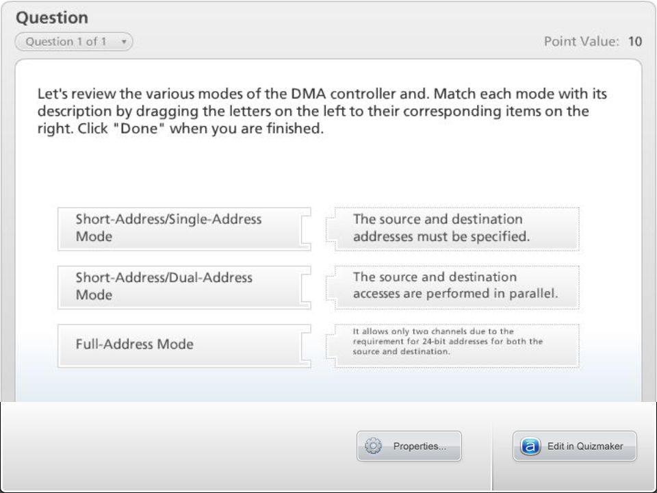
© 2008, Renesas Technology America, Inc., All Rights Reserved 17 Short-/Single-Address Mode Only a source or destination address is specified. (The other device is external.) Transfers occur in one bus cycle using DACK pin in place of address specifying I/O 1 to 65,536 transfers Sequential, Idle, and Repeat modes are supported Memory address is incremented or decremented by 1 or 2. Memory address is fixed in Idle mode Activation is via an external source A23 to A0
 Transfers occur in one bus cycle using DACK pin in place of address specifying I/O 1 to 65,536 transfers Sequential, Idle, and Repeat modes are supported Memory address is incremented or decremented by 1 or 2. Memory address is fixed in Idle mode Activation is via an external source A23 to A0.")
18
© 2008, Renesas Technology America, Inc., All Rights Reserved 18 Short-Address/Dual-Address Mode One of the addresses is 24 bits wide; the other is 16 bits wide Transfers take two bus accesses: one for read; another for write Activation sources include external request and internal functions such as 16-bit TPU and A/D A15 to A0 A23 to A0

19
© 2008, Renesas Technology America, Inc., All Rights Reserved 19 Features One of the addresses is 24 bits wide; the other is 16 bits wide. Transfers take two bus accesses: one for read; another for write 1 to 65,536 transfers Sequential, Idle, and Repeat modes are supported Memory address is incremented or decremented by 1 or 2 in Sequential and Repeat modes Memory address is fixed in Idle mode. Activation sources include 16-bit TPU, A/D, and external request Short-Address/Dual-Address Mode

20
© 2008, Renesas Technology America, Inc., All Rights Reserved 20 Full-Address Mode Both source and destination addresses are 24 bits wide. Normal and Block Transfer modes Normal mode transfer activated by auto-request or external request Block mode activated by TPU, SCI, external request or A/D converter A23 to A0 * if internal memory is used for source and destination addresses

21
© 2008, Renesas Technology America, Inc., All Rights Reserved 21 Details Both source and destination addresses are 24 bits wide Transfers take two cycles: one for read; another for write 1 to 65,536 transfers Normal and Block Transfer modes are supported Normal mode transfer activated by auto-request or external request - 1-byte or 1-word transfer executed for one transfer request - Choice of burst or cycle-steal transfer, activated by auto request Block mode is activated by TPU, SCI, external request, or A/D converter - Specified block size transfer is executed for one transfer request - Block size: 1 to 256 bytes or words Full-Address Mode

22
© 2008, Renesas Technology America, Inc., All Rights Reserved 22 DTC vs. DMAC Similarities SAR, DAR, TC Many activation sources −A/D, Timers, S/W, etc Interrupt generation Byte or word transfers Control over incrementing or decrementing SAR/DAR Normal, Repeat, and Block Transfer modes Differences DMA is faster, 1 transfer/cycle DMA is all done in H/W DMA channels are limited by H/W DMA is about 7 times faster than DTC DTC many virtual H/W channels DTC channels can be chained DTC uses on-chip RAM DTC is much more flexible

25
© 2008, Renesas Technology America, Inc., All Rights Reserved 25 Module Summary Data Transfer Controller DMA Controller DTC vs. DMAC

Similar presentations


>")


