Download presentation
Presentation is loading. Please wait.

1
Lab 2 : Overview Combinational System

2
LAB2 : Combinational Logic
A car park owner at a local shopping complex have asked for your assistance to design a sub-system that would indicate him whether his VIP car park area is full or otherwise. The reason for this request is to avoid future embarrassment on his side when facing those rich and famous and rejecting them a place to park AFTER those cars have entered into that area.

3
LAB2 : Combinational Logic
The VIP car park area has a maximum fitting of 15 luxurious cars. There are already sensors and other systems built for other purposes. What he wants you to do is to add the existing system with a sub-system that would warn him the exact amount of space left for him for easier handling.

4
LAB2 : Combinational Logic
The requirements he wants: If no cars parked; then an “EMPTY” light and a “GREEN” light will appear. If there are between 1≤cars≤10 ; then only the “GREEN” light is ON. When there are more than 10 but less than 13 cars ; a “YELLOW” light will appear and also a display will show the owner the amount of space left. When his parking lots remain 2, a “RED” warning light will flash. The display will still show the amount left. When all his spaces have been used up, the “RED” light and a “FULL” indicator will appear. The car park owner would pay you handsomely if you could prepare this sub-system to avoid future embarrassment.

5
LAB2 : Combinational Logic
GREEN RED YELLOW EMPTY FULL Combinational System a-g input (0..15 cars) Car 0 : EMPTY, GREEN Car 1-10 : GREEN Car : YELLOW, 7 SEGMENT Car : RED, 7 SEGMENT Car 15 : RED, FULL, 7 SEGMENT
 Car 0 : EMPTY, GREEN. Car 1-10 : GREEN. Car : YELLOW, 7 SEGMENT. Car : RED, 7 SEGMENT. Car 15 : RED, FULL, 7 SEGMENT.")
6
LAB2 : Combinational Logic
STEP 1 : Identify Input & Output then create a truth table STEP 2 : Draw K-Map for each output STEP 3 : Obtain minterms from K-Map STEP 4 : Draw Schematic Circuit STEP 5 : Transfer your diagram into Altera Graphic Editor STEP 6 : Simulate using waveform editor STEP 7 : Once the simulation is successful (meaning your design behave like you want it to be), then configure/assign the pin for connection. STEP 8 : Download to Altera UP2 STEP 9 : Verify your design behaviour
, then configure/assign the pin for connection. STEP 8 : Download to Altera UP2. STEP 9 : Verify your design behaviour.")
7
LAB2 : Combinational Logic
Step 1-4 : Up to schematic diagram (do it before entering the Lab) Step 5-8 : Do it in your lab. Expansion Slot Byte-Blaster Cable Altera UP2 Board Breadboard Max+Plus II Software Jumper Wire Empty Indicator Full Indicator
 Step 5-8 : Do it in your lab. Expansion. Slot. Byte-Blaster. Cable. Altera UP2. Board. Breadboard. Max+Plus II. Software. Jumper. Wire. Empty Indicator. Full Indicator.")
10
LAB2 : Combinational Logic
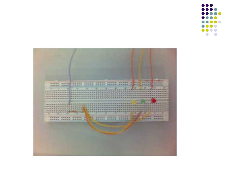
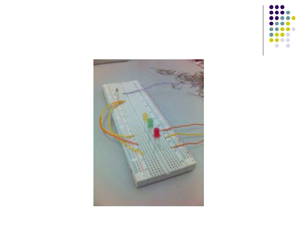
STEP 8 : Download to Altera UP2 Use the Flex Switch for input (4 bit) Use the Flex external slot pin to connect to external LED’s (Green, Yellow, Red) The external LED’s is mounted on a breadboard Use the Flex external slot pin to connect to internal LED’s (Empty and Full) BONUS Marks – display “F”-Full or “E”-Empty at FLEX Digit 1, 7 segment instead of LED’s. Use the Flex Digit 2, 7-Segment to display the available parking space.
 Use the Flex external slot pin to connect to external LED’s (Green, Yellow, Red) The external LED’s is mounted on a breadboard. Use the Flex external slot pin to connect to internal LED’s (Empty and Full) BONUS Marks – display F -Full or E -Empty at FLEX Digit 1, 7 segment instead of LED’s. Use the Flex Digit 2, 7-Segment to display the available parking space.")
11
Thank You

Similar presentations