Download presentation
Presentation is loading. Please wait.

1
CIRCUIT ANALYSIS METHOD

2
TOPIC Node-Voltage Method Mesh-current Method Source of embodiment principle Thevenin’s Circuit Norton’s Circuit Maximum Power Transfer Superposition Principle

3
INTRODUCTION TO NODE-VOLTAGE METHOD Base on Kirchhoff’s Current Law Important step: select one node as a reference.

4
Example:Node-Voltage method

5
Previous circuit, set node 3 as a reference. By using Kirchhoff’s Current law at node 1,

6
Node-voltage equation at node2

7
Solve previous equation

8
NODE-VOLTAN METHOD THAT CONTAIN DEPENDENT SOURCE If the circuit contains dependent source, the node-voltage equation imposed by the presence of the dependent source.

9
Find power that absorb by 5Ω Resistor using node-voltage method.

10
Circuit have 3 node. Need 2 node-voltage equations. Summing the currents away from node 1 generates the equation,

11
Summing the currents away from node 2 yields

12
These two node-voltage equations contain three unknowns, namely, V 1, V 2 and iø. To eliminate iø, we must express this controlling current in terms of the node-voltage,

13
Substituting this relationship into the node 2 equation simplifies the two node- voltage equations

14
Solving for V 1 and V 2 gives, V 1 =16V V 2 = 10V

15
Then, Power absorb by 5Ω resistor

16
SPECIAL CASE When a voltage source is the only element between two essential nodes, the node- voltage method is simplified.

17
Example

18
There are three essential nodes in this circuit, which means that two simultaneous equations are needed. There is only one unknown node-voltage V 2, but V 1 =100V. Solution of this circuit thus involves only a single node- voltage equation at node 2.

19
Have V 1 =100V, and solved V 2 =125V.

20
SUPERNODE A supernode is formed by enclosing a (dependent or independent) voltage source connected between two nonreference nodes and any elements connected in parallel with it.
 voltage source connected between two nonreference nodes and any elements connected in parallel with it.")
21
Example:supernode

22
Select node:

23
Node voltage equation at node 2 and node 3

24
Add previous equation

25
Previous equation could get when use supernode concept at node 2 and node 3.

26
Supernode

27
From 5Ω resistor

28
Pink equation was equal to green equation. Using supernode at node 2 and 3 make it simple to analyse the circuit.

29
Have V 1 =50V and V 3 can be describe with V 2,

30
Replace V 1 =50, V 3 and iø, pink equation become

31
Insert V 2

32
INTRODUCTION TO MESH-CURRENT METHOD One mesh mean a loop that no others loop inside. This mesh-current method used Kirchhoff’s voltage law to find current each mesh.

33
Example:Mesh-current

34
From Kirchhoff’s law (1) (2)
 (2)")
35
Use i 3 from equation (1) and insert to equation (2)
 and insert to equation (2)")
36
Mesh-current circuit with mesh current i a and i b.

37
Using KVL at those two mesh

38
After i a and i b known, then we can calculate voltage at power at each resistor.

39
MESH-CURRENT METHOD THAT HAVE DEPENDENT SOURCE When circuit have dependent source, mesh-current equation will have constant value related to dependent source.

40
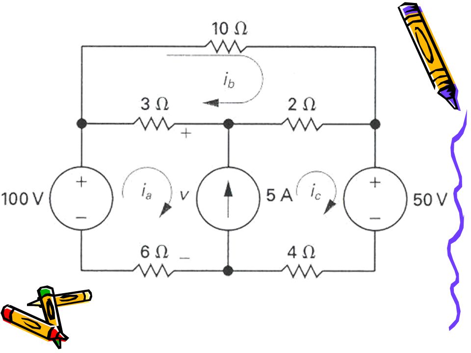
Example:mesh method with dependent source

41
Find power that obserb by 4Ω resistor using mesh-current method.

42
From Kirchhoff’s voltage law

43
Have Insert equation i ø to related equation,

44
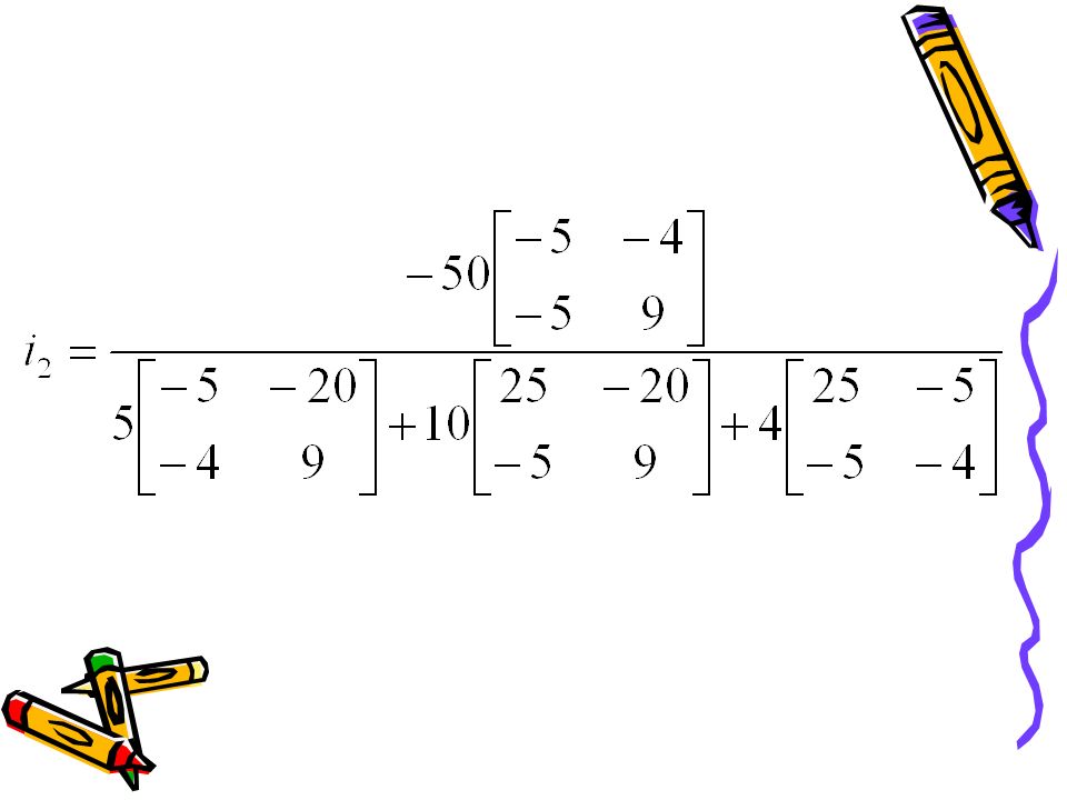
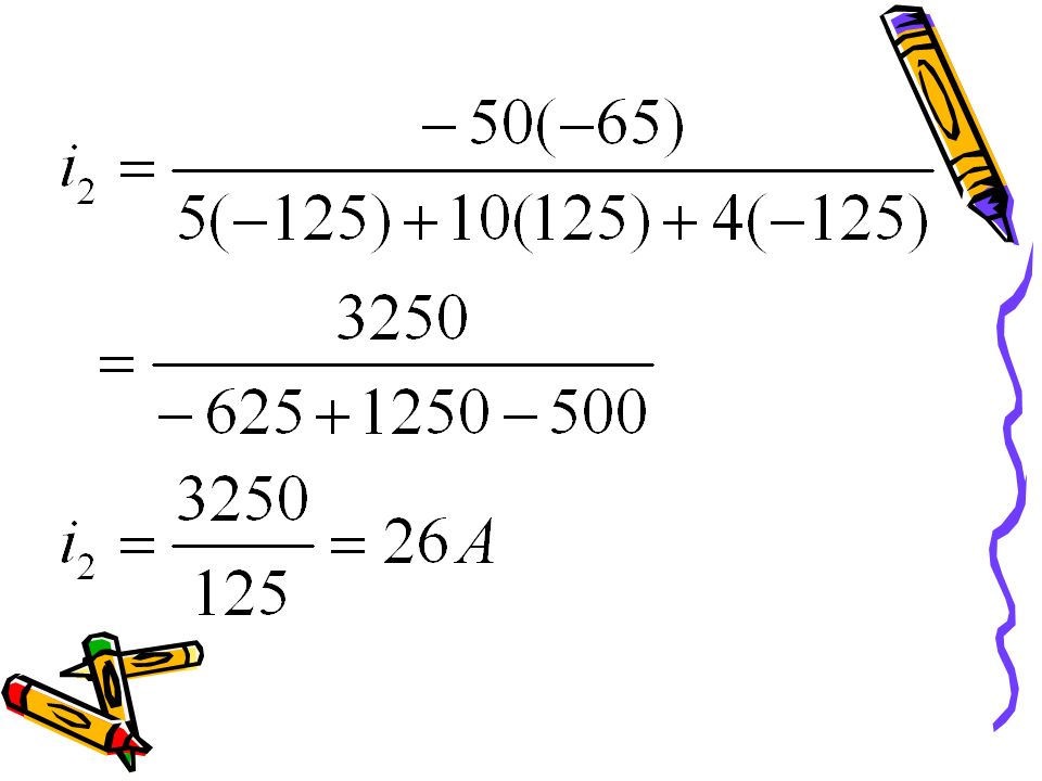
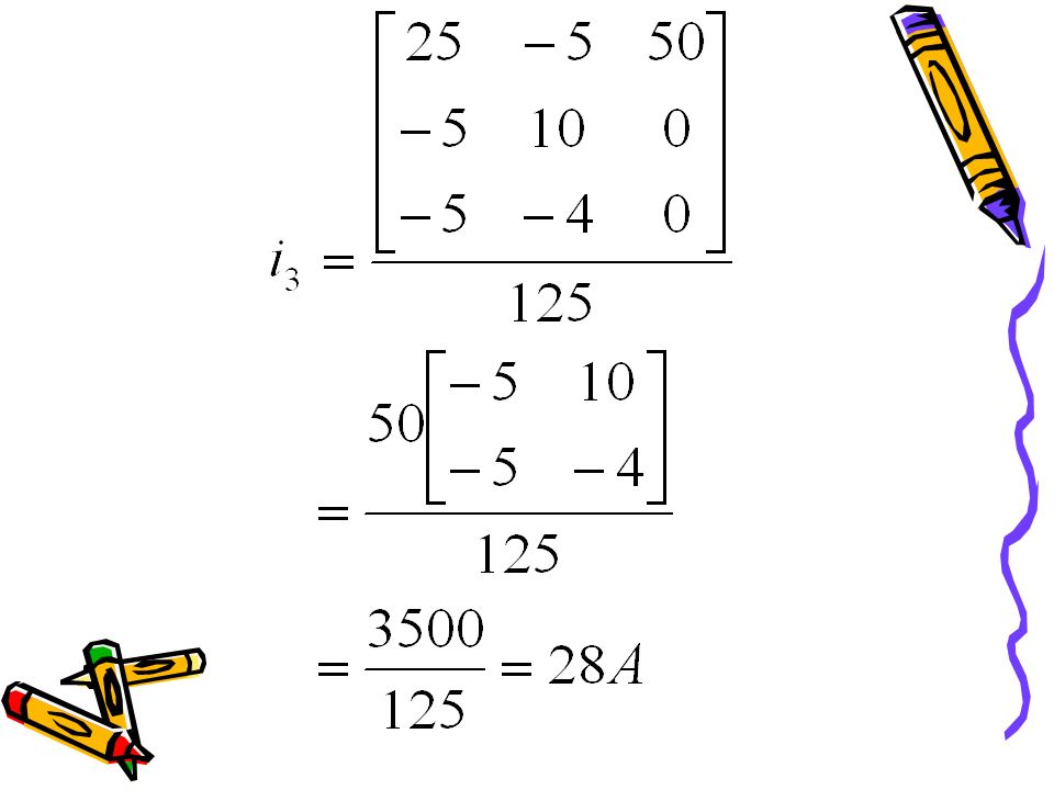
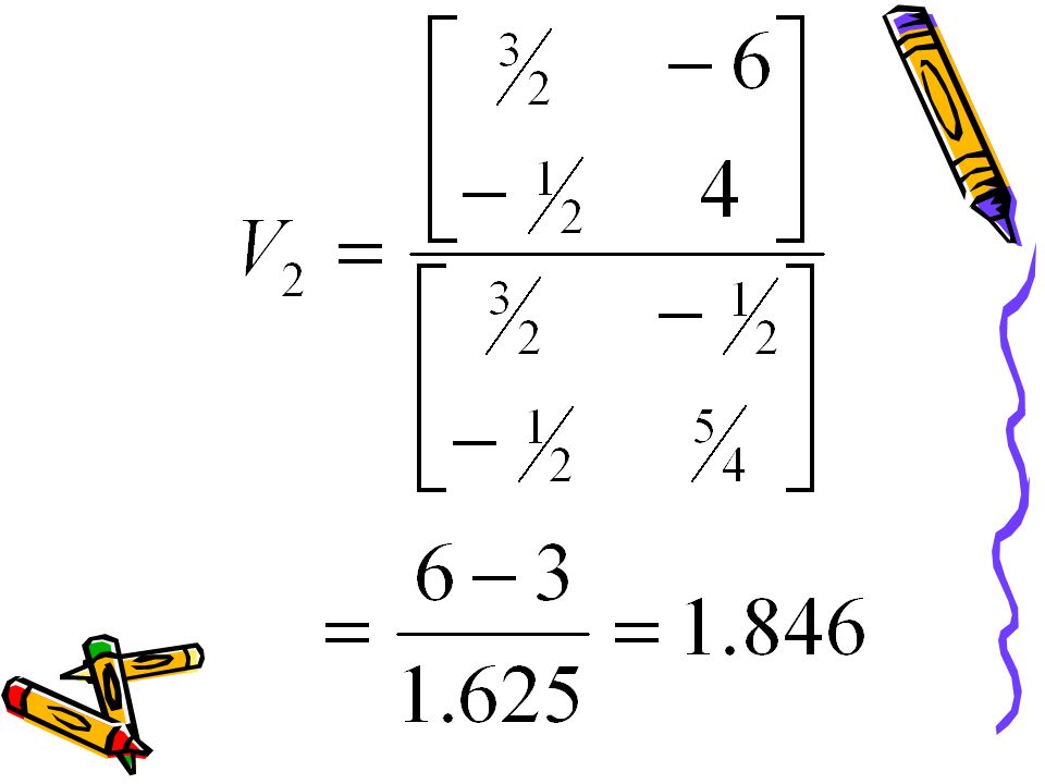
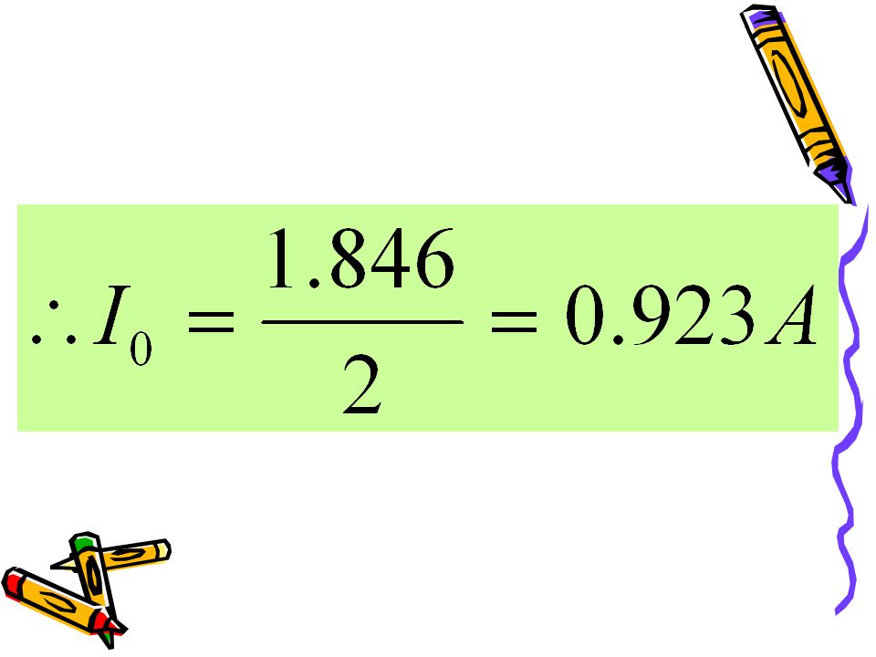
By using Cramer law, i 2 and i 3 can be calculated as below,

48
Power that absorb by 4Ω resistor

49
SPECIAL CASE (SUPERMESH) When a branch of current source can be remove and use supermesh concept (current source assume as open circuit)
 When a branch of current source can be remove and use supermesh concept (current source assume as open circuit)")
51
Assume that current source as open circuit

52
Supermesh equation

53
Mesh-current equation for mesh 2

54
Known ic –ia= 5A By using Cramer law at those three equation, value for those three mesh current could be calculated.

55
SOURCE TRANSFORMATIONS Source transformation is the process of replacing a voltage source v s in series with a resistor R by a current source i s in parallel with a resistor R, or vice versa.

56
Source Transformation

57
Example:Source transformation

58
When resistor R=0, terminal a-b become close circuit. Beginning, close circuit current should be same. Therefore,

59
Close circuit current for second circuit was Is. Therefore,

60
When resistor R = ∞, these circuit become open circuit. From first circuit, we have Vab =Vs. Therefore, it was voltage for open circuit.

61
V ab for those two circuit should be same. Therefore, V s = I s R p. Replace I s

62
Summarize for Source transformation Tetapkan MethodAfterBefore

63
Tetapkan BeforeAfterMethod

64
THEVENIN EQUIVALENT CIRCUIT Introduced in 1883 by M. Leon Thevenin (1857-1926), a French telegraph engineer.
, a French telegraph engineer..")
65
Thevenin’s theorem states that a linear two-terminal circuit can be replaced by an equivalent circuit consisting of a voltage source V Th in series with a resistor R Th where V Th is the open-circuit voltage at the terminals and R Th is the input or equivalent resistance at the terminals when the independent sources are turned off.

66
This theorem usually used to replace large sequence part (complex) with one simple equivalent circuit. This simple circuit makes voltage, current and circuit power could be calculated easily.

67
Thevenin equivalent circuit

68
Thevenin voltage, V Th = open circuit voltage for origin circuit. When load decrease until zero, circuit become close circuit and current become:

69
Example

70
Step 1: node-voltage equation for open circuit:

71
Step 2: replace close circuit at a-b terminal

72
Node voltage equation for close circuit:

73
Close circuit current: Thevenin resistance

74
Thevenin equivalent circuit

75
Norton equivalent circuit In 1926, about 43 years after Thevenin published his theorem, E. L. Norton, an American engineer at Bell Telephone Laboratories, proposed Norton’s theorem. This equivalent circuit have one independent source that parallel with one resistor.

76
Norton equivalent circuit could have from Thevenin equivalent circuit by source transformation.

77
Example Step 1: Source transformation

78
Step 2: Combine source and parallel resistors

79
Step 3: Source transformation, Series resistors combined, producing the Thevenin equivalent circuit

80
Step 4: Source transformation and Producing the Norton equivalent circuit

81
Norton equivalent circuit

82
TOPIC Node-Voltage method Mesh-current method Source transformation principle Thevenin equivalent circuit Norton equivalent circuit Maximum power transfer principle Superposition principle

83
MAXIMUM POWER TRANSFER Power system designed to provide power to load at high-efficiency and decrease power loss when delivered to load. Therefore, we need to decrease source resistance and delivering resistance.

84
Definition for Maximum power transfer tell that power that transfer from one source was represent by Thevenin equivalent circuit become max when load resistor R L and Thevenin resistor R Th was

85
Example

86
Power absorb by resistor R L

87
Differentiate p with R L

88
Differential was zero and p become maximum Solve

89
Therefore, for maximum power transfer, R L must equal with R TH. Maximum power transfer equation:

90
SUPERPOSITION PRINCIPLE The superposition principle states that the voltage across (or current through) an element in a linear circuit is the algebraic sum of the voltages across (or current through) that element due to each independent source acting alone.
 an element in a linear circuit is the algebraic sum of the voltages across (or current through) that element due to each independent source acting alone.")
91
Step to Apply Superposition Principle 1.Turn off all independent sources except one source. Find the output (voltage or current) due to that active.
 due to that active..")
92
2.Repeat step 1 for each of the other independent sources. 3.Find the total contribution by adding algebraically all the contributions due to the independent sources.

93
1.Independent voltage source become close circuit with zero volt. 2.Independent current source become open circuit. 3.If dependent source exist, it should be active while superposition process. REMEMBER !

94
Example

95
Step 1: turn off current source

96
Use voltage divider law to calculate V 0 :

97
Step 2: turn off voltage source

98
Use current divider law to calculate V 0,

99
Total V 0 : V 0 =2+5=7V.

100
Question 1

101
Answer Node 1:

102
Node 2:

105
Question 2

106
Supermesh: Mesh 3:

107
Current source known

108
Replace V 0

109
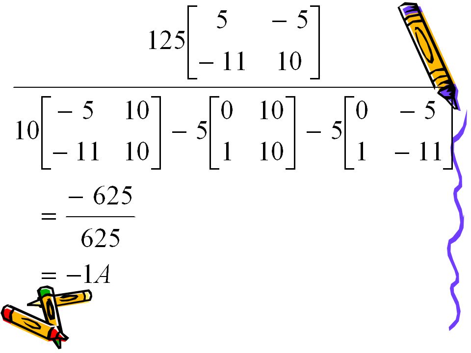
By using Cramer law

111
Current I 2 :

112
Current I 3 :

113
Question 3

114
Open circuit voltage:

115
Node-voltage equation for Voc

116
Thevenin resistance:

117
Get:

118
Question 4

119
Close circuit current

120
Norton resistance R TH = 4Ω

121
Norton equivalent circuit:

122
Question 5

123
Turn off current source

124
Turn off voltage source

125
Total V 0

126
Question 6

127
Node-voltage equation: Known: Get: V 0 =50V

128
Finally we get: V 0 =50V

Similar presentations


 method of circuit analysis Superposition method of circuit analysis Equivalent circuit.>")


