Download presentation
Presentation is loading. Please wait.

1
HiQuadLoc: An RSS-Based Indoor Localization System for High-Speed Quadrotors 1 Tuo Yu*, Yang Zhang*, Siyang Liu*, Xiaohua Tian*, Xinbing Wang*, Songwu Lu** *Shanghai Jiao Tong University **University of California at Los Angeles

2
2 Outline Motivation System Architecture Working Process Localization Algorithm Measurement and Evaluation Conclusion 2

3
Motivation In the field of indoor localization and navigation, since GPS is not available, how to locate fast-moving UAVs (Unmanned Aerial Vehicles) such as quadrotors is still a challenging topic. Most of the previous works are based on vision or ultrasound detection. 3

4
Motivation J. Eckert, R. German and F. Dressler, “On autonomous indoor flights: High-quality real-time localization using low- cost sensors,” in IEEE ICC, pp. 7093-7098, Jun. 2012. 4

5
Motivation F. Kendoul, I. Fantoni and K. Nonami, “Optic flow-based vision system for autonomous 3D localization and control of small aerial vehicles,” in Robotics and Autonomous Systems, vol. 57(6), pp. 591-602, 2009. 5
, pp ,")
6
Motivation In the field of indoor localization and navigation, since GPS is not available, how to locate fast-moving UAVs such as quadrotors is still a challenging topic. Most of the previous works are based on vision or ultrasound detection. Additional infrastructures such as off-board sensors and cameras are still needed, which leads to extra cost and energy consumption. We aim to apply the Wi-Fi fingerprint-based method, one of the most widely used technologies in indoor localization. 6

7
Motivation The existing Wi-Fi RSS-based indoor localization systems cannot be directly applied to locate high-speed quadrotors for the following reasons: ① ① Flight speed impacts localization accuracy severely. An RSS measurement will take at least 0.1s to 1s, during which the quadrotors (35km/h) would have moved for 1m to 10m. 7 Localization result MeasurementPosition
 would have moved for 1m to 10m. 7 Localization result MeasurementPosition.")
8
Motivation ② ② The workload of measuring all the RSS data in 3-D space is much higher than that in 2-D case. Some technologies such as surface-based interpolation only record the average value of RSS at each calibration point, which loses the information included in the statistical features of RSS caused by the complex channel environment. 8

9
Motivation We need to: Estimate the real flight path of a quadrotor with the limited number of times for RSS measurement; Consider the reduction in accuracy caused by the communication delay between the quadrotor and the server; Estimate the probability distributions of RSS values at most cubes, instead of estimating the average values of RSS at these cubes only. 9

10
10 Outline Motivation System Architecture Working Process Localization Algorithm Measurement and Evaluation Conclusion 10

11
System Architecture The system consists of quadrotor (smartphone) and localization server. 11
 and localization server. 11")
12
12 Outline Motivation System Architecture Working Process Off-line Stage On-line Stage Localization Algorithm Measurement and Evaluation Conclusion 12

13
Working Process: Off-line Stage ① ① Divide the localization region into cubes with constant size. ② ② Measure RSS at 1 of each 8 cubes only. ③ ③ Upload the data to the localization server. ④ ④ Process the data according to the 4-D RSS Interpolation Algorithm. 13

14
Working Process: Off-line Stage 4-D RSS Interpolation Algorithm : a cube with coordinate. We collect training data for 1 of each 8 cubes: s = 1,…,M and M is the number of APs; N is the number of training data at each cube. 14

15
Working Process: Off-line Stage The probability for to appear at is : a cube in the fingerprint map generated by AP s. Since p( ) is constant, let. It is continuous in the 4-D space We have gotten the values when 15
 is constant, let. It is continuous in the 4-D space We have gotten the values when 15.")
16
Working Process: Off-line Stage Thus we can use the cubic spline interpolation in the 4-D space to estimate when. 16 Before InterpolationAfter InterpolationReal Fingerprints

17
Working Process: On-line Stage ① ① The quadrotor sends a message to the server including the length of time slot T. Note that T must be longer than the minimal RSS measurement time according to the quadrotor’s hardware performance. 17

18
Working Process: On-line Stage ① ① The quadrotor sends a message to the server including the length of time slot T. ② ② In each time slot, the quadrotor measures RSS, and sends a message including the data to the server. The message also contains: The value of communication delay measured in the last localization process. Whether the quadrotor is turning. 18

19
Working Process: On-line Stage ① ① The quadrotor sends a message to the server including the length of time slot T. ② ② In each time slot, the quadrotor measures RSS, and sends a message including the data to the server. The message also contains: The value of communication delay measured in the last localization process. Whether the quadrotor is turning. ③ ③ The localization server estimates the position of the quadrotor, and sends the result back. 19

20
Working Process: On-line Stage ① ① The quadrotor sends a message to the server including the length of time slot T. ② ② In each time slot, the quadrotor measures RSS, and sends a message including the data to the server. The message also contains: The value of communication delay measured in the last localization process. Whether the quadrotor is turning. ③ ③ The localization server estimates the position of the quadrotor, and sends the result back. ④ ④ The quadrotor calculates the time interval between the sending out of the message and the return of the result, and sets it as the new. 20

21
Working Process: On-line Stage Turning Detection Using Direction Sensor It is hard for the client to detect the flight direction of quadrotors because a quadrotor can make lateral movements without changing its head direction. We notice that when a quadrotor is moving in a specific direction, its normal vector will have a drift angle for the same direction. 21

22
Working Process: On-line Stage During a flight, the Turning Detector periodically measures XXXX processes them by low-pass filter, and calculates 22

23
Working Process: On-line Stage If for continuous duration, the quadrotor is hovering, during which it may change its direction (turning starts). Once for another, the turning ends. 23

24
Working Process: On-line Stage Once and for more than, the quadrotor is turning. is the mean value for the recent values of α. When and for more than, the turning is ended. 24

25
25 Outline Motivation System Architecture Working Process Localization Algorithm Preliminary Localization Algorithm Path Estimation Path Fitting Location Prediction Measurement and Evaluation Conclusion 25

26
Localization Algorithm 2626 preliminary localization algorithm path estimation path fitting location prediction

27
Preliminary Localization Algorithm The algorithm is based on a frequently-used probabilistic model. Find the largest in. Its corresponding denotes the estimated location for the quadrotor. 27 4-D RSS Interpolation Algorithm The result of each RSS measurement operated by the quadrotor

28
28 Outline Motivation System Architecture Working Process Localization Algorithm Preliminary Localization Algorithm Path Estimation Path Fitting Location Prediction Measurement and Evaluation Conclusion 28

29
Path Estimation The path estimation method is based on Kalman Filter. The state of the quadrotor in the time slot: The motion model: The preliminary localization model: 29

30
Path Estimation Kalman Filter (process) 3030 Preliminary localization result Filtered Location
 3030 Preliminary localization result Filtered Location")
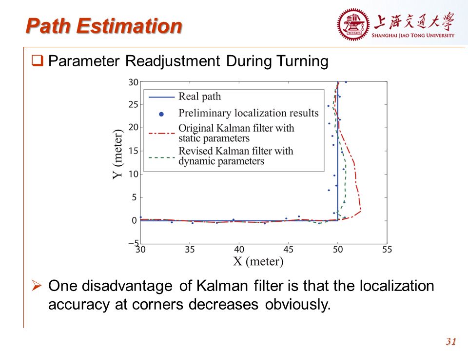
31
Path Estimation Parameter Readjustment During Turning One disadvantage of Kalman filter is that the localization accuracy at corners decreases obviously. 3131
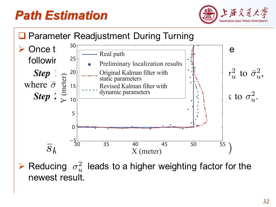
32
Path Estimation Parameter Readjustment During Turning Once the server receives a turning-start signal, the following steps are executed: Reducing leads to a higher weighting factor for the newest result. 3232
33
33 Outline Motivation System Architecture Working Process Localization Algorithm Preliminary Localization Algorithm Path Estimation Path Fitting Location Prediction Measurement and Evaluation Conclusion 33

34
Path Fitting Kalman filter works well only when its parameters match with the real case, which can hardly be satisfied since the indoor environment varies. The method of curve fitting is based on the assumption that a high-speed quadrotor tends to move in nearly straight lines. (The case of turning has been considered.) The computation complexity of 3-D curve fitting is large and is severely impacted by the initial parameters of the curvilinear function. We focus on the projected curve of the flight path on the 2- D ground. 34
 The computation complexity of 3-D curve fitting is large and is severely impacted by the initial parameters of the curvilinear function. We focus on the projected curve of the flight path on the 2- D ground. 34.")
35
Path Fitting To avoid the case that the flight path is perpendicular to the X-axis or the Y -axis, we exchange the two axes and choose the fitting function with the maximum correlation coefficient. 35

36
Path Fitting To avoid the case that the flight path is perpendicular to the X-axis or the Y-axis, we exchange the two axes and choose the fitting function with the maximum correlation coefficient. 36 Quadratic polynomial fitting

37
37 Outline Motivation System Architecture Working Process Localization Algorithm Preliminary Localization Algorithm Path Estimation Path Fitting Location Prediction Measurement and Evaluation Conclusion 37

38
Location Prediction Due to the communication delay between the client and the server, there still exists significant localization error. The delay has been uploaded. contains the estimated velocity vector of the quadrotor. Extend the motion curve of the quadrotor by The server replies the client with the final localization result. 38

39
Location Prediction Due to the communication delay between the client and the server, there still exists significant localization error. The delay has been uploaded. contains the estimated velocity vector of the quadrotor. Extend the motion curve of the quadrotor by The server replies the client with the final localization result. Note that the computation complexity of the whole algorithm is only proportional to the times of RSS measurements in a path section, which are usually O(1). Thus the response time of the server is bounded. 39
. Thus the response time of the server is bounded. 39.")
40
40 Outline Motivation System Architecture Working Process Localization Algorithm Measurement and Evaluation Conclusion 40

41
Measurement and Evaluation Evaluation of 4-D RSS Interpolation Algorithm Space: ; AP: 4 E586Bs-2 at the four corners. Full fingerprints: uses all the data collected from all the 405 cubes for localization. Interpolated fingerprints: uses the data collected from 75 cubes for localization. 41 The interpolation reduces the accuracy of localization by 0.10m to 0.17m The workload of fingerprint collection can be reduced by 81%.

42
Measurement and Evaluation 42

43
Evaluation of Localization Algorithms Compared with normal RSS-based systems, HiQuadLoc has reduced the location error by 62.8%. 43

44
Measurement and Evaluation Evaluation of Parameter Readjustment During Turning We change the values of respectively. We analyze alone to rule out the additional gain of other methods. We focus on the ±5 localization results around each corner. 44 When the error is minimum when XXXXXX respectively. It is shown that changing the parameters of Kalman filter is necessary.

45
Measurement and Evaluation Evaluation of HiQuadLoc for Different Flight Speeds We control the quadrotor to fly in a straight line for different speeds: 3m/s, 2m/s and 1m/s. 45 3m/s: average error: 2.19m, reduced by 53.0% 2m/s: average error: 1.76m, reduced by 51.0%. 1m/s, average error: 0.89m, reduced by 66.4%. Since the location error caused by delay is severer in the higher- speed case, the contribution of the location prediction method is more obvious than that in the lower-speed case.

46
46 Outline Motivation System Architecture Working Process Localization Algorithm Measurement and Evaluation Conclusion 46

47
Conclusion Our contributions: An RSS-based indoor localization system which can be applied on quadrotors moving at high speed. The methods of path estimation, path fitting and location prediction to improve accuracy. A 4-D RSS interpolation algorithm to reduce the workload by more than 80% during the offline data training phase. The results of experiments show that HiQuadLoc reduces the average location error by more than 50% compared with normal RSS-based systems. 4747

48
Thank You

Similar presentations
 Professor:>")


