Download presentation
Presentation is loading. Please wait.

1
Layer Two Data Link Layer Collects bits from layer 1 and organizes into frames Passes bits that make up frames to layer 1 for transmission Concerned with transmission between neighbors, not necessary the ultimate destination. At this layer, frames are sometimes referred to interchangeably as packets The term packet is best used at the layer 3 or Network Layer and the term frame best used at the Data Link Layer

2
Data Link Layer Provides framing – collects bits into frames There are different ways to construct frames May provide Flow Control – controlling the rate of data flow between two stations May provide Error Detection Variety of error detection mechanisms Provides for Error Control – implements mechanisms to handle detected errors This requires very specific Data Link protocols

3
Framing Framing varies with each hardware technology Various items may be included in the construction of a frame Addressing information Character counts Special beginning/ending characters Special beginning/ending flags (special bit string) Error detection bits or characters Data Many early used special protocol characters for framing – sometimes called character oriented protocols Special characters also used for station dialog
 Error detection bits or characters Data Many early used special protocol characters for framing – sometimes called character oriented protocols Special characters also used for station dialog")
4
Examples of Special Protocol Characters Sample framing characters SYNSynchronization Character STXStart of Text ETXEnd of Text SOHStart of Header ETBEnd of Block Sample Station Dialog Characters ENQEnquiry NAKNegative acknowledgement ACKAcknowledgement EOTEnd of transmission

5
Examples of Frames SYN SYN EOT Control Frame SYN SYN STX ETX CC Data Frame DATA Error Control

6
Transparency The special framing and dialog characters among the 256 possible byte configurations At times, these can occur naturally as part of the data stream We must be able to distinguish a particular data byte from one being used as a special character This is called transparency This is accomplished by using another special character called an escape character, also called a Data Link Escape (DLE)
")
7
Transparency To address this problem, some schemes preceded every control character in the data stream with the escape character. Thus, STX becomes DLE STX At the receiver, if a DLE is received, it is removed and the following character is considered part of the data This is called character or byte stuffing If the sequence DLE appears in the data, an additional DLE is inserted in front of the DLE in the data. At the receiver, when two consecutive DLE characters are received, they are replaced with a single DLE character and considered part of the data.

8
Transparency SYN SYN STX ------ STX ----------------- EOT --------------- ETX SYN SYN STX ------ DLE STX ------------- DLE EOT ---------------- ETX Stuffed bytes Transparent frame

9
More Framing Character oriented protocols are not well suited for many applications not based on 8 bit characters. To address these limitations other framing techniques were developed. In these families of protocols, frames are delimited with a special bit pattern, called a flag This flag is inserted at the beginning and end of a frame, thus defining the boundaries 0 1 1 1 1 1 1 0 flag

10
Transparency (again) What if this ‘flag’ occurs naturally in the data? Rule is: if there are 5 consecutive 1 bits, the transmitter inserts an extra ‘0’ bit This is called bit stuffing In this way, 6 consecutive 1 bits can only occur as part of a flag When the receiver receives 5 consecutive 1 bits, it removes the next 0 bit

11
Transparency Given the following frame to send 0 1 1 0 1 1 1 1 1 1 1 1 1 0 0 0 1 1 1 1 1 0 1 Transmitter sends 0 1 1 1 1 1 1 0 0 1 1 0 1 1 1 1 1 0 1 1 1 1 0 0 0 1 1 1 1 1 0 0 1 0 1 1 1 1 1 1 0 FLAG

12
Framing Protocol Early protocols were character oriented Bisync Arpanet DECNET Bit oriented protocols Synchronous Data Link Control (SDLC) – IBM ISO modified SDLC and adopted a standard called High Level Data Link Control (HDLC) ITU developed a modified protocol called Link Access Protocol (LAP) and (LAPB) – used with modems These are all bit oriented protocols
 – IBM ISO modified SDLC and adopted a standard called High Level Data Link Control (HDLC) ITU developed a modified protocol called Link Access Protocol (LAP) and (LAPB) – used with modems These are all bit oriented protocols")
13
HDLC Frame 0111110 Address Control data FCS 0111110

14
ERRORS ERRORS ERRORS Transmission are subject to a variety of errors Electrical noise or spikes Microwave fading Thermal noise Errors usually occur in burst Good in some way – if we had frames of 1000 bits and an error rate of.001, on average we couldn’t transmit any frame cleanly Bad in some ways – it is more difficult to detect multiple bit errors in a frame

15
Error Detection General approach We have a message of m data bits We append 1 or more (say r) bits. These r bits are check bits to help detect errors We send a total message n = m + r bits The number r depends on the particular technique used

16
Parity We are familiar with adding a parity bit to each character In the case of a 7 bit ASCII character m = 7 bits r = 1 bit We require that the number of 1 bits in the character be always even or always odd Example: G _ 1 0 0 0 1 1 1 0 1 0 0 0 1 1 1 I _ 1 0 0 1 0 0 1 1 1 0 0 1 0 0 1

17
Parity Detects all single bit errors Detects all odd number of bit errors Does not detect even number of bit errors But, parity can do much more if we organize data differently

18
Parity Consider the following ASCII string TESTING 1 0 1 0 0 1 0T 1 0 0 0 1 0 1E 1 0 1 0 0 1 1S 1 0 1 0 0 1 0T 1 0 0 1 0 0 1I 1 0 0 1 1 1 0N 1 0 0 0 1 1 1G 1 101100101100 1 0 1 0 1 1 00 m = 49 r = 15 n = 64 1

19
Parity Detects any single bit error Detects any double bit errors Detects any burst error of length equal or less then the number of columns Problems Overhead Errors still get by

20
Checksums Consider a frame as a set of 16 bit words 32 bit words Perform some arithmetic (addition) on the collection of words Add all the words If a carry results, add in to the next word The result (16 bit or 32 bit) is called a checksum Transmit checksum along with frame Receiver performs same arithmetic and compares result
 on the collection of words Add all the words If a carry results, add in to the next word The result (16 bit or 32 bit) is called a checksum Transmit checksum along with frame Receiver performs same arithmetic and compares result")
21
Checksum Advantages Checksum has small overhead compared to frame size Simple to calculate on the fly Disadvantages Fails to catch many common errors 71 FC

22
Cyclic Redundancy Checks CRC Consider modulo 2 arithmetic Addition 1 0 0 1 1 0 1 1 1 1 0 0 1 0 1 0 0 1 0 1 0 0 0 1 Subtraction 1 1 1 1 0 0 0 0 1 0 1 0 0 1 1 0 0 1 0 1 0 1 1 0 Addition and subtraction is identical to Exclusive OR No carry No borrow

23
CRC Division is done as described, modulo 2 Thus, a divisor goes into a dividend if the dividend has as many bits as divisor 1 1 0 1 1 1 0 0 0 1 0 1 1 1 1 Remainder

24
CRC Consider M = m bits of a message F = r check bits T = (m + r ) bit frame Let P be an (r + 1) sequence of bits (to be determined) We would like to determine P so that it evenly divides T We could write T = 2 r * M + F
 bit frame Let P be an (r + 1) sequence of bits (to be determined) We would like to determine P so that it evenly divides T We could write T = 2 r * M + F")
25
CRC We have T = 2 r * M + F 2 r * M = Q + R P P If we wish P to evenly divide T T = 2 r * M + F = Q + R + F P P What happens if we choose F = R ? Then T = Q + R + R P P P Remainder is ? 0

26
CRC CRC calculation Take m data bits Append r 0 bits (2 r * M) Divide by some agreed up P of length (r + 1) Append that remainder as r bits to the m data bits Transmit T = m + r Receiver performs the same calculation on the entire frame If result is zero, receiver assume no error If non zero, assumes a transmission error
 Divide by some agreed up P of length (r + 1) Append that remainder as r bits to the m data bits Transmit T = m + r Receiver performs the same calculation on the entire frame If result is zero, receiver assume no error If non zero, assumes a transmission error")
27
CRC Example M = 6 bits 1 1 0 0 1 1 P = 5 bits 1 1 0 0 1 r = 4 bits T = 6 + 4 = 10 bit frame 1 1 0 0 1 1 1 0 0 1 1 0 0 1 1 1 0 0 1 0 0 0 01 0 1 00 0 0 1 0 0 1 Remainder T = 1 1 0 0 1 1 1 0 0 1

28
CRC Example Receiver must know P = 1 1 0 0 1 Receiver calculates T/P 1 1 0 0 1 1 1 0 0 1 1 1 0 0 1 1 1 0 0 1 1 0 1 1 0 0 1 0 0 0 0 1 1 1 0 0 1 0 Remainder Frame accepted

29
CRC Error Detection 1 1 0 0 1 1 1 0 1 1 1 1 0 1 1 1 1 0 0 1 1 1 0 1 1 0 0 0 1 1 1 1 1 0 0 1 1 1 1 1 1 1 1 0 0 1 1 1 0 1Remainder Error Detected

30
CRC Conventions P is a bit string of length r + 1 If r is large, difficult to express as a bit string By convention we express it as a polynomial Example P = 1 1 0 0 1 P = 1*X 4 + 1*X 3 + 0*X 2 + 0*X 1 + 1*X 0 or P = X 4 + X 3 + 1

31
Standard CRC Polynomials CRC-12 = X 12 + X 11 + X 3 + X 2 + X + 1 CRC-16 = X 16 + X 15 + X 2 + 1 CRC-CCITT = X 16 + X 12 + X 5 + 1 CRC-32 = X 32 + X 26 + X 23 + X 22 + X 16 + X 12 + X 11 + X 10 + X 8 + X 7 + X 5 + X 4 + X 2 + X + 1

32
CRC Effectiveness Detects all single or double bit errors Detects all burst errors of length r or less Detects 99.99+ of all burst errors larger than r Calculation seem complicated but can be performed by simply using a shift register and exclusive-or gates Usually implemented in hardware

33
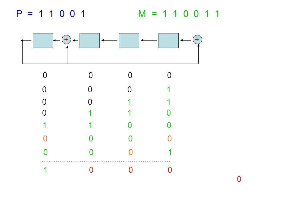
++ Hardware Implementation of CRC Construct a shift register of size r Use Exclusive-OR gates preceding each term is a coefficient of 1 in the polynomial Given P = 1 1 0 0 1 P = 1 1 0 0 1

34
++ P = 1 1 0 0 1 M = 1 1 0 0 1 1 11001100001100110000 0 0 0 0 T

35
++ P = 1 1 0 0 1 M = 1 1 0 0 1 1 100110000100110000 0 0 0 0 0 0 0 1

36
++ P = 1 1 0 0 1 M = 1 1 0 0 1 1 0011000000110000 0 0 0 0 0 0 0 1 0 0 1 1

37
++ P = 1 1 0 0 1 M = 1 1 0 0 1 1 01100000110000 0 0 0 0 0 0 0 1 0 0 1 1 0 1 1 0

38
++ P = 1 1 0 0 1 M = 1 1 0 0 1 1 110000110000 0 0 0 0 0 0 0 1 0 0 1 1 0 1 1 0 1 1 0 0

39
++ P = 1 1 0 0 1 M = 1 1 0 0 1 1 110000110000 0 0 0 0 0 0 0 1 0 0 1 1 0 1 1 0 1 1 0 0 1 0 0 0 0

40
++ P = 1 1 0 0 1 M = 1 1 0 0 1 1 1000010000 0 0 0 0 0 0 0 1 0 0 1 1 0 1 1 0 1 1 0 0 1 0 0 0 0

41
++ P = 1 1 0 0 1 M = 1 1 0 0 1 1 00000000 0 0 0 0 0 0 0 1 0 0 1 1 0 1 1 0 1 1 0 0 0 0 0 0 0 0 0 1

42
++ P = 1 1 0 0 1 M = 1 1 0 0 1 1 0 0 0 0 0 0 0 0 1 0 0 1 1 0 1 1 0 1 1 0 0 0 0 0 0 0 0 0 1........................................................... 1 0 0 0
43
++ P = 1 1 0 0 1 M = 1 1 0 0 1 1 0 0 0 0 0 0 0 1 0 0 1 1 0 1 1 0 1 1 0 0 0 0 0 0 0 0 0 1........................................................... 1 0 0 0 1 1 0 0 1 CRC

Similar presentations

 Synchronous Networks recover.>")


