Download presentation
Presentation is loading. Please wait.

1
Head works

2
Structure at the intake of the tunnels and flumes

3
They have Booms Trash racks Sluices for passing debris
Gates and valves for controlling the flow

4
Booms Divert ice and floating logs from intake
Consists of logs tied end to end and form a floating chain to diverts floating matter to a by-pass chute

5
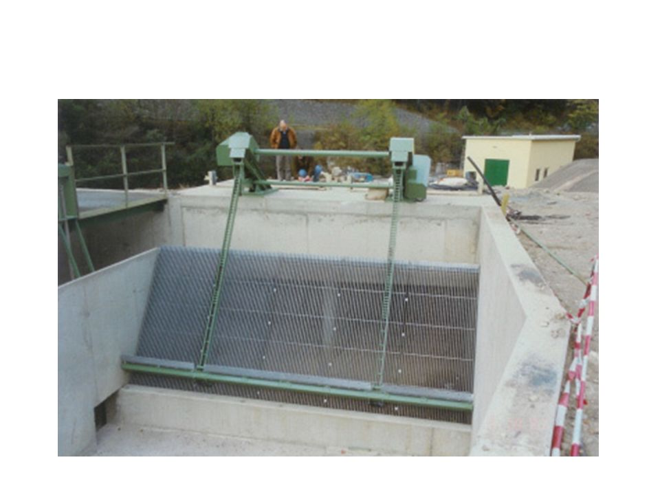
Trash racks Remove floating or submerged debris directly at the intake entrance. Placed across the intake structure to keep out floating matter from going through the penstock.

6
They form a screen of oarallel bars welded to cross members and supported by beams
Spacing of bars varies from 1.5 to 15cm or more Smaller the spacing greater the safety Gates control the rate of water flow entering

10
Low pressure intake with headworks

11
High pressure or high headworks

12
Gates like Cylindrical Spherical
Butterfly of needle valves are used for water control These gates are used at headworks penstocks turbine inlets

13
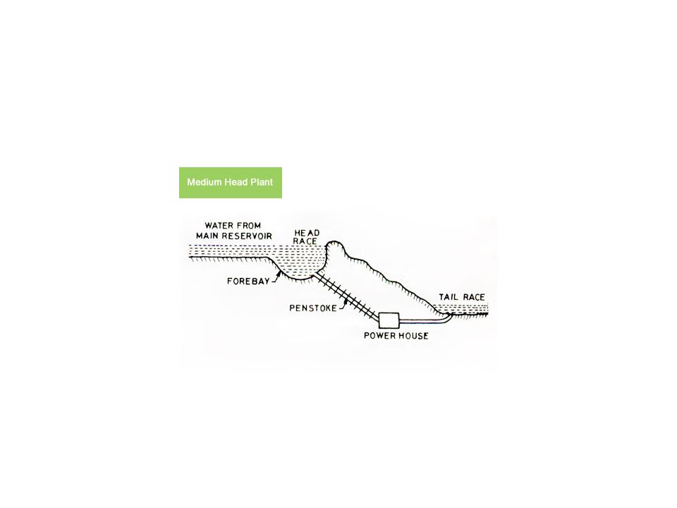
Conduits Headrace Tail race Leads water from headwork to turbine
Leads water rom turbine outlet ot downstram side of plant

14
Conduits Open type Closed type flumes Canals tunnels Pipe lines
penstocks

15
Flumes It’s an artificial water channel of wood, metal , concrete or masonry supported above the surface of the ground. Used when its expensive to construct canals Commonly used to cross a depression or difficult terrain

16
Usually rectangular or semi circular type
Bench flumes--- flumes that are directly supported on ground

17
Wooden flume

18
Steel flume

19
Concrete flume

20
Concrete flumes have longer life
Low maintenance cost Wooden flumes have shorter life

21
Tunnels Water carrying tunnels Service tunnels --- dry tunnels
Diversion tunnels To divert water away Head race or power tunnels Carry water to power house These are pressure tunnels Tail race tunnels carry water away from the power house

22
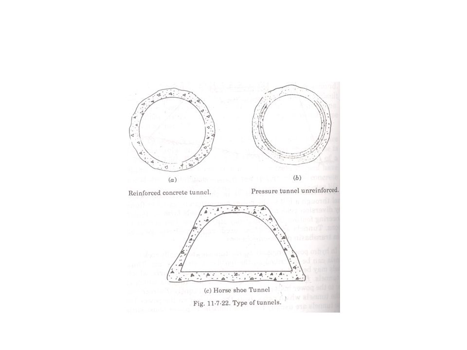
Cross section of tunnels
Circular or horse shoe when water flow is full tunnel acta as a pressure conduit These tunnels are to be lined Steel or concrete liner is necessary to prevent collapse if tunnel material is weak During partial flow acts as open channels No need for lining

24
Forebay Water carried by the power canals is distriuted to various penstocks through forebay Forebay is also called head pond Water is temporarily stored in case of load rejection Water is withdrawn when load increases Acts as a regulating reservoir

25
Forebay is created at the end of the power canal by
widening it into a small basin Constructing a small dam across the natural flow The excess water accumulated is discharged by spillways

27
Main Parts of a typical forebay
Entrance bay or basin Spillway Flushing device Screens Valve chamber Conduit or penstock inlet

28
Penstock Pipe connecting forebay or surge tank to turbine
Pressure conduit

29
Choice of penstock materials
Depends on Head Topography of terrain Discharge to be handled

30
Materials Steel Rcc Asbestos cement Wood Cast steel

31
Sharp bends to be avoided
They cause loss of head Require special anchorages Anchorage prevents penstock movement due to dynamic forces

Similar presentations


>")


. 2. Waterway-Waterway (syphon or.>")


. Dimensioning and Constructing (Drawing 4) Main Procedures 1. Determination.>")