Download presentation
Presentation is loading. Please wait.

1
Chapter 9 Design Automation Techniques

2
After completing this chapter, you will be able to – Create iMates – Create and place iParts – Create iAssemblies – Create iFeatures – Create Design View Representations – Create Flexible Assemblies – Create Positional Representations – Create Overlay Drawing Views Chapter 9 - Objectives

3
After completing this chapter, you will be able to – Improve Assembly Capacity and Performance – Detect Contact in Assemblies – Mirror an Assembly – Copy an Assembly – Create Assembly Work Features – Create Assembly Features – Work with 2D Components in Assemblies – Locate tools related to the Content Center, Design Accelerator, and Frame Generator Chapter 9 – Objectives continued

4
iMates Apply assembly constraints –Matching iMate Create in part file Constraints: Mate, Flush, Tangent, Insert or Motion

5
iMates Browser entry Glyph on part Rename

6
iMates Insert Component –Use iMate Match List –Search order

7
Composite iMates Group multiple iMates into a single, composite iMate Browser – highlight iMates, right- click

8
Publish iMates Change existing assembly constraints to iMates

9
iMates alt+Drag & Visibility Alt+drag – displays iMates iMate visibility –Browser –Graphics window

10
Exercise 9-1 Creating and Using iMates

11
iParts –Store parameters and properties information –Create unique parts based on stored information –Example - Bushing iPart Single file Table with 3 rows (members) –Unique Hole Dia –Unique Material –Unique Filename
 –Unique Hole Dia –Unique Material –Unique Filename")
12
iParts Creation Stage –Design the part –Establish all possible versions in a table Each row of the table is a member Multiple members = iPart Factory Placement Stage –Select a member from the iPart Factory –Insert the member into an assembly

13
Types of iParts Standard iPart (Factories) –Values cannot be modified –Features cannot be added Custom iPart (Factories) –Unique value for at least one variable –Features can be added
 –Values cannot be modified –Features cannot be added Custom iPart (Factories) –Unique value for at least one variable –Features can be added")
14
iParts Creating iParts Tools > Create iPart iPart Author Dialog –Add parameters –Define Keys Primary Secondary (Up to 9)
")
15
iParts iPart Author Dialog –Working with Members Adding Members > Insert Row Removing Members > Delete Row Modifying Members and Setting Default

16
Creating iParts iPart Author Dialog –Custom iParts Custom Parameter Column Custom Parameter Cell –Specify a value for the parameter upon iPart placement

17
Default iPart and Options Set default row Options –Part Number –Member Name

18
Creating iParts iPart Author Dialog –Click OK The part is converted to an iPart Factory Table saved as an embedded Microsoft Excel spreadsheet Table icon is displayed in the Browser

19
Editing iParts Operations –Delete table Converts iPart back to a part –Modify parameters & properties –Add or Delete members –Edit Options Edit Table Edit via Spreadsheet –Spreadsheet formulas, conditional statements, etc. are shown as red cells

20
Placing iParts Place Component tool –Standard & Custom iPart Placement dialog box Custom – enter value from the custom column Folder is created with same name as the iPart Factory Folder is checked for existing members when placed Folder is created in same location as the factory by default

21
Auto-Capture iParts Create iParts while editing iPart or iAssembly –Edit Member Scope

22
Drawing From iParts Create drawing view –Model State tab –Select component

23
Table From iParts Table tool –Select a view

24
Exercise 9-2 Creating and Placing iParts

25
iAssemblies iAssemblies are used to group a set of similar designs in a table format –Assembly Configurations –Similar to iParts – Create within an assembly (iam) file
 file")
26
Component tab = lists the components of the assembly with configurable items –Member = configuration –Each row = one configuration Author Dialog Box

27
Parameters Tab – Include in the factory: –Constraints –Assembly features –Work features –iMates –Component patterns –Other parameters such as user parameters

28
Author Dialog Box Properties Tab – Allows the inclusion and modification of: –Summary –Project –Physical –Custom properties

29
Exclusion Tab – Similar to the Parameters list, shows all objects that can be excluded, including components. Can also be set on the Components tab, but provides a more specific way to view and set the exclusion property Author Dialog Box

30
iMate, BOM and Other Tab –iMates Lists each iMate with offset value, include/exclude, matching name, and sequence number available for configuration –BOM Specify bill of material specific properties –Other Specify a custom column that can contains a string value. Custom columns can be designated as keys or as a filename.

31
Exercise 9-3 Working with iAssemblies

32
iFeatures Capture design intent –Name –Size –Position Include Placement Help Represented with Custom Icons Stored as separate files (.IDE)
")
33
iFeatures Tools > Extract iFeature Create iFeature dialog box –Selected Features –Size Parameters Range and Limit –Position Geometry

34
iFeatures Insert iFeature tool –Part Features Panel Bar Insert iFeature dialog box –Select –Position –Size –Precise Position

35
iFeatures Editing iFeatures –Open the.ide file in Autodesk Inventor Edit iFeature View Catalog iFeature Author Table –Edit iFeature Opens the Create iFeature dialog box –Cannot change parameters –Can modify size parameters and position geometry »Name »Value »Limit »Prompt

36
iFeatures Table-Driven iFeatures –Open the.ide file in Autodesk Inventor –iFeature Author Table iFeatures behave similar to iParts –Main difference: No File Name, Display Style or Material column designations

37
iFeatures Table-Driven iFeatures –Inserting Same as inserting typical iFeatures Key parameters are a drop-down list Custom parameters are specified in the dialog box

38
Exercise 9-4 Creating and Placing iFeatures

39
Design View Representations Save configurations that show the assembly in different states, stores the following –Component visibility (visible or not visible) –Component selection status (enabled or not enabled) –Color settings and style characteristics applied in the assembly –Zoom magnification –Viewing angle
 –Component selection status (enabled or not enabled) –Color settings and style characteristics applied in the assembly –Zoom magnification –Viewing angle")
40
Create New Design View Representation Make Active Rename Lock Public vs. Private Design Views Design View Representations

41
New Design View Representation Make Active – check mark Lock – view changes are not reflected in locked Design View Representation Design View Representations

42
Set Design View when placing an assembly file –Options button –Select Design View Design View Representations

43
Make Design View in a subassembly active –Select from list Design View Representations

44
Same as a Public Design View Representation buts creates an IDV file Should accompany assembly file Private Design View Representations

45
Select Representation from list Associative – Yes / No Drawings From Design View Representations

46
Flexible Assemblies Set Flexible property to a subassembly to allow movement independent from other occurrences of the subassembly

47
Flexible Assemblies Right-click on the subassembly in browser or graphics window and click Flexible from the menu.

48
Positional Representations Create a motion study of an assembly model –Based on positional representation

49
Positional Representations Override Settings for an assembly constraint –Rename –Override

50
Positional Representations Override Settings for an assembly constraint –Suppression –Value

51
Positional Representations Edit Positional Representation –Panel Bar –Spreadsheet

52
Positional Representations Create Base Views based on Positional Representation

53
Level of Detail –Copy to Level of Detail –Improve performance Design View Representations

54
Creating Overlay Views Overlay views document positional representations of an assembly in a single view.

55
Exercise 9-5 Positional Representations

56
Capacity and Performance Improve the performance when creating drawing files. Effect the preview of the view and increase performance by reducing what is displayed prior to view creation –Application Options > Drawing tab –Show Preview As All Components, Partial, and Bounding Box Section View Preview as Uncut Memory Saving Mode

57
Capacity and Performance Improve the performance when creating drawing files. Effect the preview of the view and increase performance by reducing what is displayed prior to view creation –Application Options > Drawing tab –Use Bitmap for Shaded Views Always or Offline Only Image Fidelity Memory Saving Mode –Preview Option

58
Capacity Meter Capacity meter shows –Number of the left displays the number of occurrences in the active file –Number on the right displays the number of files in the session. –A memory graph or meter displays the amounts of system RAM and amount of RAM that is free

59
Levels of Detail Representations Improve capacity and performance in modeling and drawing environments –Suppress components –Right-click on component Browser Graphics Window

60
Levels of Detail Representations In assembly file –Expand Representations folder –Select required Level of Detail Open existing assembly –Click Options –Select required Level of Detail

61
Levels of Detail Representations Creating a drawing view of an assembly select a Level of Detail Representation to be used from the drawing view dialog box.

62
Contact Detection Solver Determines how assembled components behave when a mechanical motion is applied Activate Contact Solver

63
Contact Detection Solver Add components to set –Browser –Graphics Window Under constrained components

64
Contact Detection Solver Driven constraint –Contact will drive under constrained components that are in the Contact Set

65
Mirroring Components in an Assembly Mirror assembly components or an entire assembly in the current design file In an assembly click the Mirror Components tool

66
Mirroring Components in an Assembly Select a plane to mirror components about

67
Mirroring Components in an Assembly Select components to mirror and select operation for each component

68
Mirroring Components in an Assembly More area of the dialog box –Reuse Standard Content and Factory Parts –Preview Components Mirrored Reuse Standard Content

69
Mirroring Components in an Assembly File Names –Prefix –Suffix –Naming Scheme

70
Copying Components in an Assembly Copy assembly components or an entire assembly in the current design file –Copy Components tool –Select components in graphics screen or Browser

71
Copying Components in an Assembly Select components to copy and select operation for each component

72
Copying Components in an Assembly File Names –Naming Scheme Prefix Suffix

73
Exercise 9-6 Mirroring Assembly

74
Assembly Work Features Create work planes and axes between parts in an assembly by selecting edges or points on parts. These work features remain tied to each associated part and adjust accordingly as the assembly is modified

75
Assembly Features Assembly features are features that are defined in an assembly Only affect a part when the part is viewed in the context of the assembly Assembly features only remove material

76
Assembly Sketched In an assembly sketch on a part’s: –Face –A part’s work plane –An assembly work plane

77
Assembly Feature Tools Assembly features exist only at the assembly level They do not affect the individual part files

78
Assembly Feature Removing and Adding Participants

79
Exercise 9-7 Creating Assembly Features

80
2D Design Layout Function before form Create a new part Sketch 2D geometry Add assembly constraints

81
Exercise 9-8 Creating a 2D Design Layout

82
Content Center Library of standard components Place components while in an assembly

83
Content Center Publish feature to Content Center Publish components to Content Center

84
Design Accelerator Create complex parts and features based on engineering data such as ratio, torque, power, and material properties. The Design Accelerator consists of: –Component generators –Mechanical calculators –Engineer’s Handbook

85
Frame Generator Create frame structures –Skeleton part (modeling)
")
86
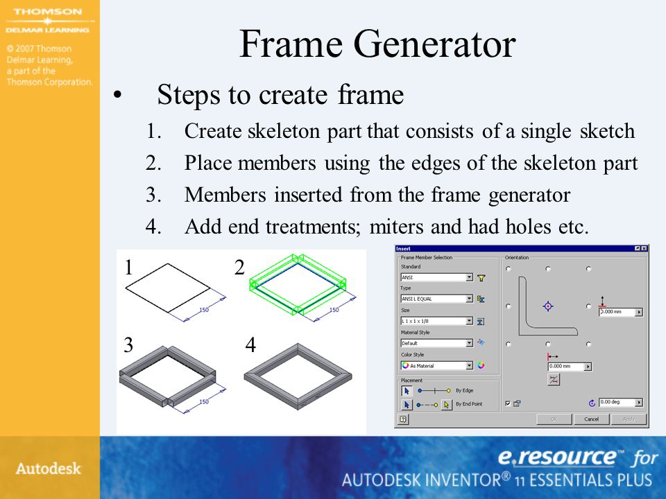
Frame Generator Steps to create frame 1.Create skeleton part that consists of a single sketch 2.Place members using the edges of the skeleton part 3.Members inserted from the frame generator 4.Add end treatments; miters and had holes etc. 1 43 2
87
Summary ToDo This Create an iMateClick the Create iMate tool from the Panel Bar or click Create iMate on the Tools menu. Create a Composite iMateCTRL + Select the single iMates in the Browser, right- click and select Create Composite from the menu. Create an iPartClick Create iPart on the Tools menu. Create a custom iPartRight-click a column in the iPart Author dialog and select Custom Parameter Column. Place an iPartClick Place Component tool from the Assembly Panel Bar. Create an iAssemblyClick Create iAssembly on the Tools menu. Place an iAssemblyClick Place Component tool from the Assembly Panel Bar. Create an iFeatureClick Extract iFeature on the Tools menu.

88
Summary ToDo This Insert an iFeatureClick Insert iFeature on the Part Features Panel Bar or toolbar. Create a Design View Representation Click the Design View Representations tool at the top of the Browser. Create a Flexible AssemblyIn the Browser, right-click an assembly and click Flexible from the menu. Create a Positional Representation In the Browser, right-click the Position node and select New from the menu. Create an Overlay Drawing View Click the Overlay tool. Create a Level of Detail Representation In the Browser, right-click the Level of Detail node and select New Level of Detail from the menu. Mirror an AssemblyClick the Mirror Components tool and select the top level assembly in the Browser. Copy an AssemblyClick the Copy Components tool and select the top level assembly in the Browser.

89
Project Exercise Chapter 9

90
Applying Your Skills Skill Exercise 9-1

Similar presentations


 with Excel>")


