Download presentation
Presentation is loading. Please wait.

1
Digital Logic Structures: Chapter 3 COMP 2610 Dr. James Money COMP 2610 1

2
Gated D Latch Two inputs: D (data) and WE (write enable) – when WE = 1, latch is set to value of D S = NOT(D), R = D – when WE = 0, latch holds previous value S = R = 1
 and WE (write enable) – when WE = 1, latch is set to value of D S = NOT(D), R = D – when WE = 0, latch holds previous value S = R = 1")
3
Register As we have seen before, it is usually convenient to work in quantities of more than one bit at a time Many times, we use 16 bits such as on the LC-3 computer We want to store and read these as self contained units

4
Register Let us consider an example, for simplicity, of a 4 bit register The four bit value stored in the register is Q 3, Q 2, Q 1, Q 0 The value D 3, D 2, D 1, and D 0 can be written if WE is asserted

5
Register

6
A common shorthand notation is to describe a sequence of bits that are numbered as above as Q[3:0] Each bit is assigned it’s own number The rightmost bit is bit [0] and the leftmost is bit [n-1] for n bits
![A common shorthand notation is to describe a sequence of bits that are numbered as above as Q[3:0] Each bit is assigned it’s own number The rightmost bit is bit [0] and the leftmost is bit [n-1] for n bits](http://images.slideplayer.com/25/8242728/slides/slide_6.jpg "A common shorthand notation is to describe a sequence of bits that are numbered as above as Q[3:0] Each bit is assigned it’s own number The rightmost bit is bit [0] and the leftmost is bit [n-1] for n bits")
7
Register Consider the 16 bit pattern 0011101100011110 Bit [15] is 0, bit [14] is 0, bit [13] is 1, and so on Bit [0] is 0, bit [1] is 1, and bit [2] is 1
![Register Consider the 16 bit pattern Bit [15] is 0, bit [14] is 0, bit [13] is 1, and so on Bit [0] is 0, bit [1] is 1, and bit [2] is 1](http://images.slideplayer.com/25/8242728/slides/slide_7.jpg "Register Consider the 16 bit pattern Bit [15] is 0, bit [14] is 0, bit [13] is 1, and so on Bit [0] is 0, bit [1] is 1, and bit [2] is 1")
8
Register We can also designate a subunit of the pattern by Q[l:r], where l is the leftmost bit and r is the rightmost bit We call such a unit a field
![Register We can also designate a subunit of the pattern by Q[l:r], where l is the leftmost bit and r is the rightmost bit We call such a unit a field](http://images.slideplayer.com/25/8242728/slides/slide_8.jpg "Register We can also designate a subunit of the pattern by Q[l:r], where l is the leftmost bit and r is the rightmost bit We call such a unit a field")
9
Register If A[15:0] is our example before of 0011101100011110 Then, – A[15:12] is 0011 – A[13:7] is 1110110 – A[2:0] is 110 – A[1:1] is 1
![Register If A[15:0] is our example before of Then, – A[15:12] is 0011 – A[13:7] is – A[2:0] is 110 – A[1:1] is 1](http://images.slideplayer.com/25/8242728/slides/slide_9.jpg "Register If A[15:0] is our example before of Then, – A[15:12] is 0011 – A[13:7] is – A[2:0] is 110 – A[1:1] is 1")
10
Register Note that the numbering scheme from right to left is arbitrary We could of course number left to right In many cases, we use right to left in practice

11
Concept of Memory We now have all the tools to describe memory on a computer Memory is made up of a large number of locations, each uniquely identifiable Each location can store a value

12
Concept of Memory The unique identifier of each memory location is called an address We refer to the number of bits stored at each address as its addressability You might have 16MB of memory This means there is 16 million addresses(in base 2 at least) and each address is 8 bits
 and each address is 8 bits")
13
Address Space We refer to the total number of address as the memory’s address space With n bits for an address, we can have up to 2 n locations 16MB = 16 * (1024)*1024 = 2 24 bytes
*1024 = 2 24 bytes")
14
Addressability The addressability is the number of bits stored at each address In our example before, the addressability was 8 bits or 1 byte Most computers are byte addressable for historic reasons

15
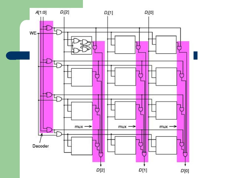
A 2 2 -by-3-bit Memory In the example, the memory has an address space of 4 locations and addressability of 3 bits Accessing memory requires decoding the address bits The address decoder takes A[1:0] and asserts one line
![A 2 2 -by-3-bit Memory In the example, the memory has an address space of 4 locations and addressability of 3 bits Accessing memory requires decoding the address bits The address decoder takes A[1:0] and asserts one line](http://images.slideplayer.com/25/8242728/slides/slide_15.jpg "A 2 2 -by-3-bit Memory In the example, the memory has an address space of 4 locations and addressability of 3 bits Accessing memory requires decoding the address bits The address decoder takes A[1:0] and asserts one line")
17
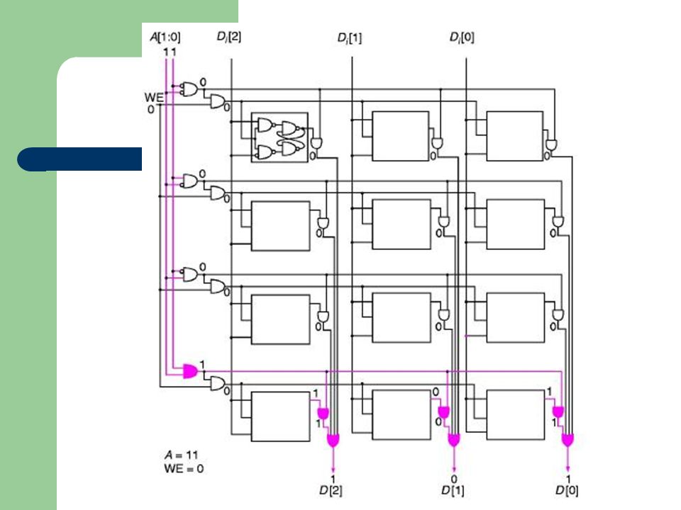
A 2 2 -by-3-bit Memory We say the word line is being addresses in this example Each row is a word line Memory can be read by using the correct value for A[1:0]
![A 2 2 -by-3-bit Memory We say the word line is being addresses in this example Each row is a word line Memory can be read by using the correct value for A[1:0]](http://images.slideplayer.com/25/8242728/slides/slide_17.jpg "A 2 2 -by-3-bit Memory We say the word line is being addresses in this example Each row is a word line Memory can be read by using the correct value for A[1:0]")
Similar presentations


>")


>")


 Yonsei University 1 st Semester, 2015 Sanghyun Park.>")


