Download presentation
Presentation is loading. Please wait.

1
D75P 34R - HNC Computer Architecture Week 6 Boolean Logic © C Nyssen/Aberdeen College 2004 All images © C Nyssen /Aberdeen College unless otherwise stated George Boole courtesy of Roger Parsons/ Lincoln Cathedral First transistor ©Bell Labs USA Decision Making © Microsoft Prepared 2/11/04

2
Boolean Logic is a branch of mathematics. It deals with rules for manipulating the two values true and false. Boolean Logic is particularly relevant to computers as it is binary logic. Deals with only two values Can only be in one state at any given point in time Can’t be between states Time taken to jump between states is negligible In other words, 1 = true and 0 = false!

3
George Boole (1815 - 1864) was an English mathematician, the first to develop and describe a formal system of working with truth values. He was born in 1815 as the son of a shoemaker in Lincoln. Young George was taught maths by his father, but by the age of eight, had outgrown his father's self-taught limits, and a tutor was hired to teach him Latin. At 16 he became an assistant teacher, at 20 he opened his own school. He went on to become the first Professor of Mathematics at University College Cork, despite having no degree himself. His books The Mathematical Analysis of Logic (1847) and An Investigation of the Laws of Thought (1854) form the basis of present-day computer science and cybernetics.
 and An Investigation of the Laws of Thought (1854) form the basis of present-day computer science and cybernetics..")
4
A Boolean expression is any expression that evaluates out to true or false. Is the expression 1+3 a Boolean expression? What about 1+3=7? Other examples - x > 100 y < z a = 100 w <> 10

5
We can use Boolean Operators to construct more complex Boolean operations. The first three we will look at are AND, OR and NOT. Some examples are - X > 100 AND x < 250 A = 0 OR B > 100 NOT x = 100

6
Boolean Logic Gates are built from transistors. These are tiny switches built of semiconductor material, usually silicon. If the gate is open, no current can flow (0 state). If the gate is closed, current can flow (1 state).
. If the gate is closed, current can flow (1 state)..")
7
The simplest gate of all is the NOT gate, or INVERTER All this does is reverse the value that went in. We already saw an example of this when calculating 1’s complements. The Logic Circuit for a NOT gate looks like this -

8
The Truth Table for a NOT gate looks like this Example - If x = 10 and y = 15 NOT X > 0 is FALSE NOT X > Y is TRUE We write NOT A as A 00 01 10 11

9
We can show how a NOT works in Pascal using this routine - VAR choice: char; {more stuff here} write (‘Enter a number from 0 - 6’); readln (choice); IF NOT (choice IN [‘0’..’6’]) THEN BEGIN {to run error handling routine} write (‘Error! Enter a number from 0 - 6!’); readln (choice); END[if}; We are actually running a check on what choice is NOT as opposed to what it is!
![We can show how a NOT works in Pascal using this routine - VAR choice: char; {more stuff here} write (‘Enter a number from 0 - 6’); readln (choice); IF NOT (choice IN [‘0’..’6’]) THEN BEGIN {to run error handling routine} write (‘Error.](http://images.slideplayer.com/33/8204957/slides/slide_9.jpg "Enter a number from 0 - 6!’); readln (choice); END[if}; We are actually running a check on what choice is NOT as opposed to what it is!.")
10
The next gate is the AND gate. It always takes at least two inputs. All of the inputs have to be TRUE before the outcome is also TRUE. The logic gate for an AND looks like this -

11
The truth table for AND looks like this - Example If x = 10 and y = 15 x > 0 AND y < 20 is TRUE x = 10 AND x > y is FALSE We write A AND B as A.B 001 010 100 110

12
We can show how an AND works in Pascal using this routine - VAR BlindDateIsAttractive: boolean; MoneyInPocket: integer; {more stuff here} IF (BlindDateIsAttractive = true) AND (MoneyInPocket > 100) THEN writeln (‘Let’s go to Poldinos!’) ELSE writeln (‘Lets go to Burger King.’); {endif} Both conditions have to be true before it will go on to do the statement after the THEN.
 AND (MoneyInPocket > 100) THEN writeln (‘Let’s go to Poldinos!’) ELSE writeln (‘Lets go to Burger King.’); {endif} Both conditions have to be true before it will go on to do the statement after the THEN.")
13
The next gate is the OR gate. Again, it needs at least two inputs. But unlike the AND, only ONE of the inputs has to be TRUE before the outcome is also TRUE. The logic gate for an OR looks like this -

14
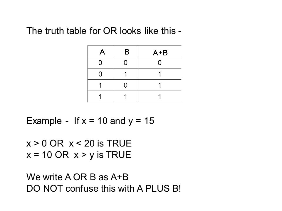
The truth table for OR looks like this - Example - If x = 10 and y = 15 x > 0 OR x < 20 is TRUE x = 10 OR x > y is TRUE We write A OR B as A+B DO NOT confuse this with A PLUS B! 000 011 101 111
15
We can show how an OR works in Pascal using this routine - VAR DayOfWeek: String; {more stuff here} IF (DayOfWeek = ‘Friday’) OR (DayOfWeek = ‘Saturday’) THEN writeln (‘Let’s go out clubbing!’) ELSE writeln (‘Better stay home and study’); {endif} Only one of the conditions has to be true before it will go on to do the statement after the THEN.
 OR (DayOfWeek = ‘Saturday’) THEN writeln (‘Let’s go out clubbing!’) ELSE writeln (‘Better stay home and study’); {endif} Only one of the conditions has to be true before it will go on to do the statement after the THEN.")
16
Let’s try some examples of Boolean Expressions. ((x = 10) OR (y = 10)) AND (z > x) True Assume that x = 10, y = 15 and z = 20. X = 10 Y = 10 z > x
 OR (y = 10)) AND (z > x) True Assume that x = 10, y = 15 and z = 20. X = 10 Y = 10 z > x.")
17
(x = y) OR (NOT (x > z)) True Assume that x = 10, y = 15 and z = 20. x > z x = y
 OR (NOT (x > z)) True Assume that x = 10, y = 15 and z = 20. x > z x = y")
18
Assume that x = 10, y = 15 and z = 20. ((x = y) AND (x = 10)) OR (y > z) False x = y x = 10 y > z
 AND (x = 10)) OR (y > z) False x = y x = 10 y > z")
19
Assume that x = 10, y = 15 and z = 20. NOT ((x > y) AND (z > y) AND (x < z)) True x > y z > y x < z
 AND (z > y) AND (x < z)) True x > y z > y x < z")
20
As part of your assessment material, you will be asked to perform logical operations between pairs of binary numbers. Example - Perform a logical AND between the numbers 0001 0100 0010 0011

21
A logical OR between the same two numbers - 1111 1111 1110 1111

22
The next gate you need to be able to use is the XOR (exclusive OR) gate. Again, it needs at least two inputs. Unlike the AND and OR, however, it needs the inputs to be DIFFERENT from each other for a TRUE output. If all of the inputs are the same, whether they are true or false, the output will be FALSE. The logic gate for an XOR looks like this -

23
The truth table for XOR looks like this - Example If x = 10 and y = 15 x > 0 XOR y < 20 false x = 10 XOR x > ytrue We write A XOR B as A + B Sometimes you will see XOR written as EOR. 000 011 101 110

24
A logical XOR between the same two numbers - 1110 1011 1100 1100

25
In addition to the basic gates, there are also three composite gates - NAND, NOR and XNOR. These comprise - an AND immediately followed by a NOT an OR immediately followed by a NOT an XOR immediately followed by a NOT To perform the logical operation, just treat the numbers as a normal AND, OR or XOR, then reverse the result!

26
The logic gates for NAND, NOR and XNOR look like this -

27
The Truth Tables for NAND, NOR and XNOR - 001 010 100 110 001 011 101 110 001 010 100 111

28
Logic gates are the basic building blocks of any computer system. Using combinations of logic gates, complex circuits can be constructed.

29
Summary [1]. Boolean Expressions are expressions that evaluate to either TRUE or FALSE. We can use the operators NOT, AND, OR, XOR, NAND, NOR and XNOR. Boolean Logic is particularly compatible with computers as both work in a bistable environment.
![Summary [1]. Boolean Expressions are expressions that evaluate to either TRUE or FALSE.](http://images.slideplayer.com/33/8204957/slides/slide_29.jpg " We can use the operators NOT, AND, OR, XOR, NAND, NOR and XNOR. Boolean Logic is particularly compatible with computers as both work in a bistable environment..")
30
Summary [2] NOT (inverter) reverses any input. AND requires ALL inputs to be TRUE for a TRUE output. OR requires only ONE input to be TRUE for a TRUE output. XOR requires differences in the inputs for a TRUE output. NAND is equivalent to an AND immediately followed by a NOT. NOR is equivalent to an OR immediately followed by a NOT. XNOR is equivalent to an XOR immediately followed by a NOT.
![Summary [2] NOT (inverter) reverses any input.](http://images.slideplayer.com/33/8204957/slides/slide_30.jpg " AND requires ALL inputs to be TRUE for a TRUE output. OR requires only ONE input to be TRUE for a TRUE output. XOR requires differences in the inputs for a TRUE output. NAND is equivalent to an AND immediately followed by a NOT. NOR is equivalent to an OR immediately followed by a NOT. XNOR is equivalent to an XOR immediately followed by a NOT..")
Similar presentations


