Download presentation
Presentation is loading. Please wait.

1
Chapter 4. Angle Modulation

2
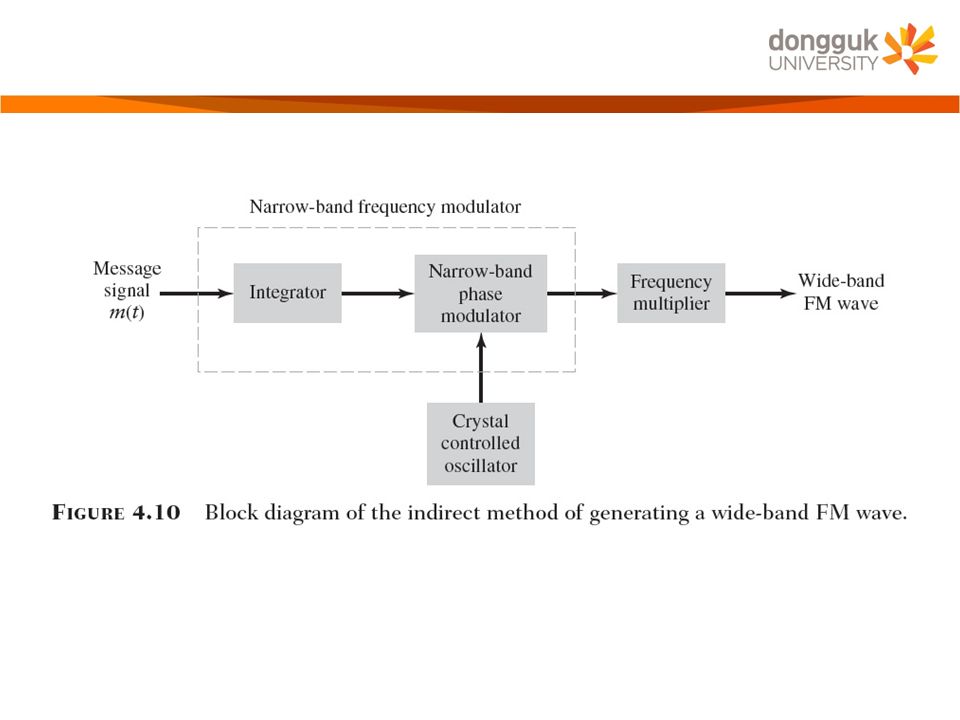
4.7 Generation of FM Waves Direct Method –A sinusoidal oscillator, with one of the reactive elements in the tank circuit of the oscillator being directly controllable by the message signal –The tendency for the carrier frequency to drift, which is usually unacceptable for commercial radio applications. –To overcome this limitation, frequency stabilization of the FM generator is required, which is realized through the use of feed- back around the oscillator Indirect Method : Armstrong Modulator –The message signal is first used to produce a narrow-band FM, which is followed by frequency multiplication to increase the frequency deviation to the desired level. –Armstrong wide-band frequency modulator The carrier-frequency stability problem is alleviated by using a highly stable oscillator

4
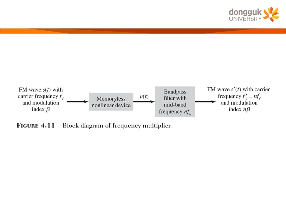
–A Frequency multiplier A memoryless nonlinear device The input-output relation of such a device is A new FM wave is

6
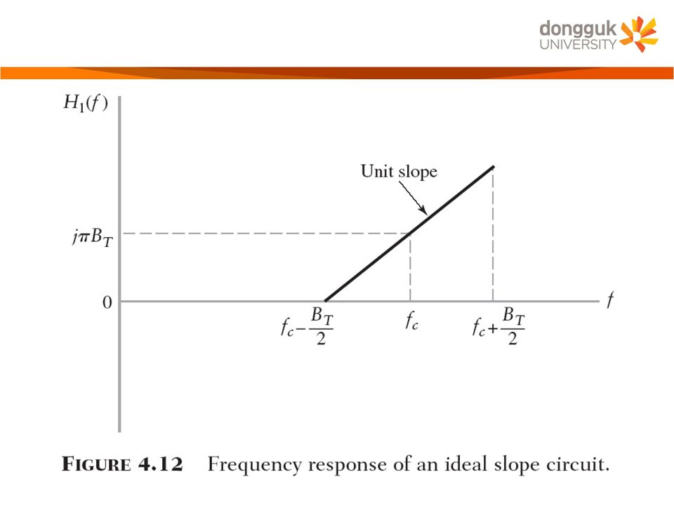
4.8 Demodulation of FM Signals Frequency Discriminator –The FM signal is We can motivate the formulation of a receiver for doing this recovery by nothing that if we take the derivative of Eq. (4.44) with respect to time A typical transfer characteristic that satisfies this requirement is
 with respect to time A typical transfer characteristic that satisfies this requirement is.")
7
–The slope circuit The circuit is also not required to have zero response outside the transmission bandwidth –The complex envelope of the FM signal s(t) is
 is")
9
Multiplication of the Fourier transform by j2πf is equivalent to differentiating the inverse Fourier transform Application of the linearity property to the nonzero part of yields the actual response of the slope circuit due to the FM wave s(t) is given by
 is given by")
10
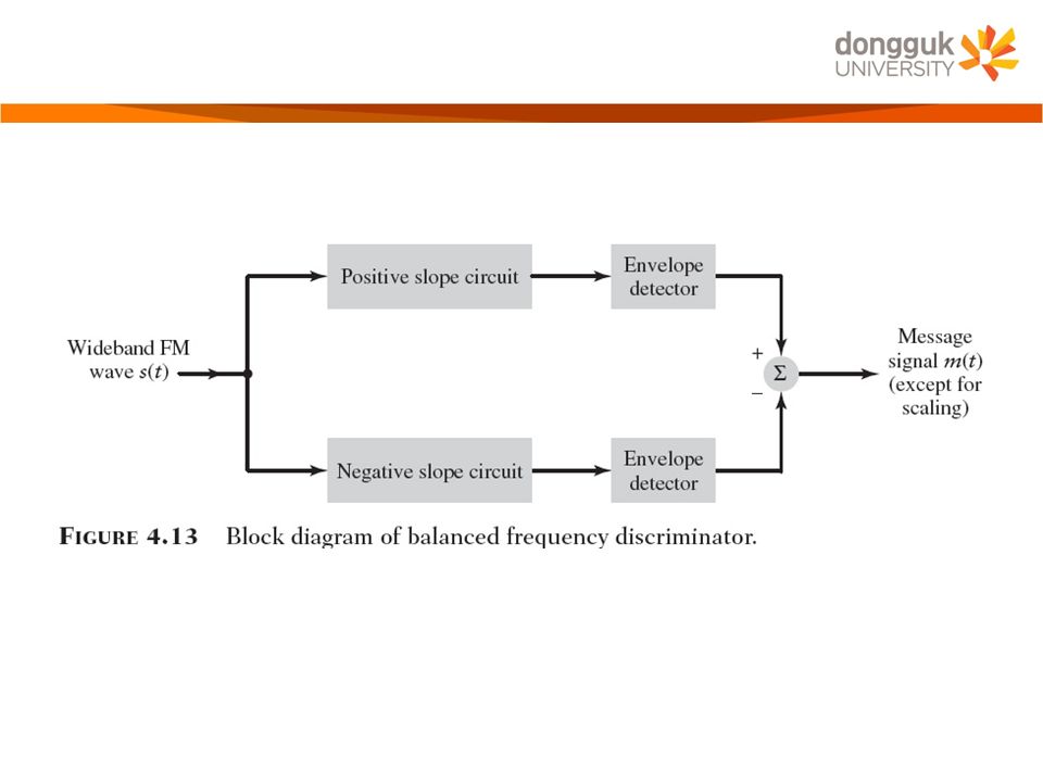
The envelope detector Under ideal conditions, the output of the envelope detector is The overall output that is bias-free

12
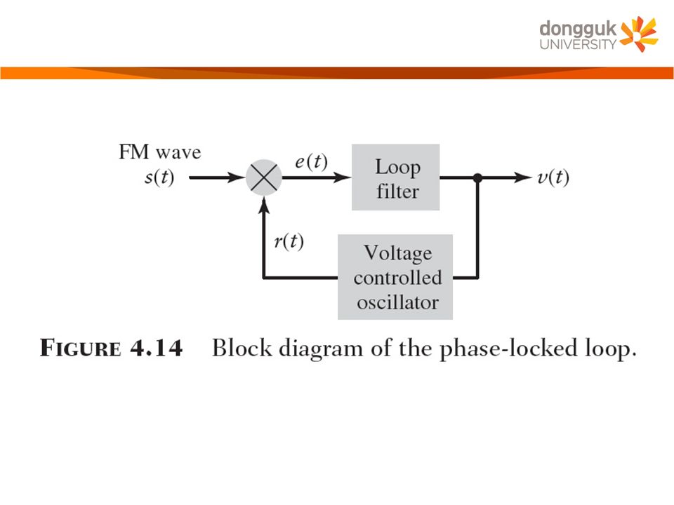
Phase-Locked Loop –A feedback system whose operation is closely linked to frequency modulation –Three major components Voltage-controlled oscillator (VCO) Multiplier Loop filter of a low-pass kind –Fig. 4.14, a closed-loop feedback system –VCO has bee adjusted so that when the control signal is zero, two conditions are satisfied The frequency of the VCO is set precisely at the unmodulated carrier frequency f c of the incoming FM wave s(t) The VCO output has a 90 ◦ -degree phase-shift with respect to the unmodulated carrier wave.
 The VCO output has a 90 ◦ -degree phase-shift with respect to the unmodulated carrier wave..")
14
–Suppose the incoming FM wave is –The FM wave produced by the VCO as –The multiplication of the incoming FM wave by the locally generated FM wave produces two components A high-frequency component A low-frequency component

15
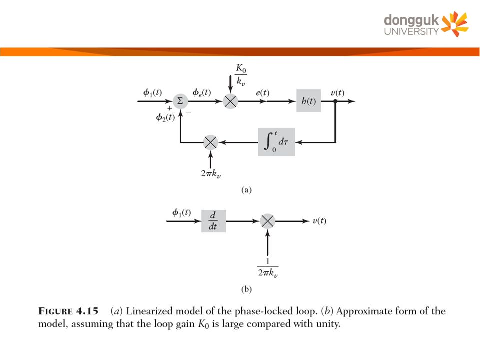
–Discard the double-frequency term, we may reduce the signal applied to the loop filter to –The phase error is –Eq. (4.62), (4.63), (4.65), and (4.60)constitute a linearized feedback model of the phase-locked loop Loop-gain parameter of the phase lock loop
, (4.63), (4.65), and (4.60)constitute a linearized feedback model of the phase-locked loop Loop-gain parameter of the phase lock loop.")
16
The inverse of this feedback path is described in the time domain by the scaled differentiator The closed-loop time-domain behavior of the phase-locked loop is described by the overall output v(t) produced in response to the angle Φ 1 (t) in the incoming FM wave s(t) The magnitude of the open-loop transfer function of the phase-locked loop is controlled by the loop-gain parameter K 0 When the open-loop transfer function of a linear feedback system has a large magnitude compared with unity for all frequencies, the closed-loop transfer function of the system is effectively determined by the inverse of the transfer function of the feedback path.
 produced in response to the angle Φ 1 (t) in the incoming FM wave s(t) The magnitude of the open-loop transfer function of the phase-locked loop is controlled by the loop-gain parameter K 0 When the open-loop transfer function of a linear feedback system has a large magnitude compared with unity for all frequencies, the closed-loop transfer function of the system is effectively determined by the inverse of the transfer function of the feedback path.")
17
–We may relate the overall output v(t) to the input angle Φ 1 (t) by
 to the input angle Φ 1 (t) by")
19
4.10 Summary and Discussion Two kinds of angle modulation –Phase modulation (PM), where the instantaneous phase of the sinusoidal carrier wave is varied linearly with the message signal –Frequency modulation (FM), where the instantaneous frequency of the sinusoidal carrier wave is varied linearly with the message signal Frequency modulation is typified by the equation FM is a nonlinear modulation process In FM, the carrier amplitude and therefore the transmitted average power is constant Frequency modulation provides a practical method for the tradeoff of channel bandwidth for improved noise performance.
, where the instantaneous phase of the sinusoidal carrier wave is varied linearly with the message signal –Frequency modulation (FM), where the instantaneous frequency of the sinusoidal carrier wave is varied linearly with the message signal Frequency modulation is typified by the equation FM is a nonlinear modulation process In FM, the carrier amplitude and therefore the transmitted average power is constant Frequency modulation provides a practical method for the tradeoff of channel bandwidth for improved noise performance.")
Similar presentations
>")
 Carrier Wave Modulation Systems.>")

 مدولاسیون های موج پیوسته 1.>")


 Fall 2008 NCTU EE Tzu-Hsien Sang.>")


