Download presentation
Presentation is loading. Please wait.

2
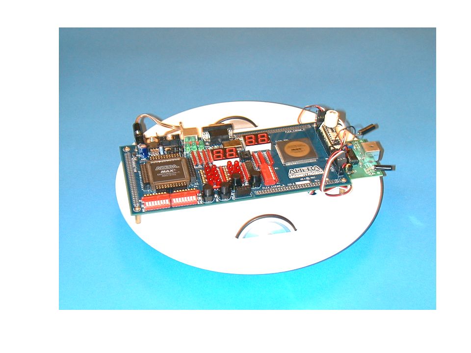
Figure 12.1 The UP1-bot.

3
Figure 12.2 Left: Radio Control Servo Motor and Right: Servo with Case and Gears Removed.

6
Figure 12.3 Line Tracker Module – 3 LEDs and Phototransistors are mounted on bottom of board

7
Figure 12.4 IR Proximity Sensor Module – Two IR LEDs on sides and one IR sensor in middle.

8
Figure 12.5 Proximity detector active sensor area.

9
Figure 12.6 Circuit layout of one LED and the receiver module on the infrared detector.

10
Figure 12.7 Polaroid Sonar Module – Left: Sonar Transducer and Right: Controller Board.

11
Figure 12.8 Dinsmore 1490 Digital Compass Sensor.

12
Figure 12.9 UP1-bot Plexiglas Base with wheel slots and drill hole locations.

13
Figure 12.10 Bottom view of UP1-bot base showing battery, servos and cabling.

14
Figure 12.11 Top View of UP1-bot Base with Compass and IR Proximity Sensor Modules.

Similar presentations


 Josh Bingaman Ryan Hitchler John Maitin Fabien Nervais Matt Sharp Capstone Fall 2004.>")


