Download presentation
Presentation is loading. Please wait.

1
Medical Imaging Ultrasound Edwin L. Dove 1412 SC edwin-dove@uiowa.edu 335-5635

3
3D Reconstruction

4
Ultrasound Principle When you shout into a well, the sound of your shout travels down the well and is reflected (echoes) off the surface of the water at the bottom of the well. If you measure the time it takes for the echo to return and if you know the speed of sound, you can calculate the depth of the well fairly accurately.

5
Ultrasound Principle Ultrasound is sound having a frequency greater than 20,000 cycles per second, that is, sound above the audible range Medical ultrasound is sound having a frequency greater than 2-100 MHz Medical ultrasound imaging is sound that is converted to an image

6
Medical Ultrasound Advantages of acoustic energy: –can be directed in a beam –obeys the laws of reflection and refraction –reflected off object borders –no known unwanted health effects Disadvantages of acoustic energy: –propagates poorly through a gaseous medium –reflected off of borders of small objects –quickly dissipates (as heat)
")
7
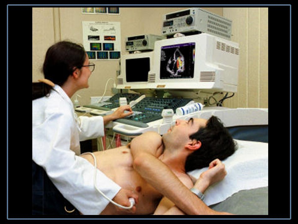
Why Ultrasound in Cardiology? Portable, relatively cheap Non-ionizing During the echocardiogram, it is possible for the cardiologist to: –Watch the heart’s motion – in 2D real-time –Ascertain if the valves are opening and closing properly, and view any abnormalities –Determine the size of the heart chambers and major vessels –Measure the thickness of the heart walls –Calculate standard metrics of health/disease e.g., Volume, EF, SV, CO –Dynamic evaluation of abnormalities

8
Ultrasound Theory Pressure (ultrasound) wave produced by vibrating source “Listen” for reflection Build image by sending wave in different directions
 wave produced by vibrating source Listen for reflection Build image by sending wave in different directions")
9
Sinusoidal pressure source

10
Quantitative Description p pressure applied in z-direction density viscosity

11
Speed of Sound in Tissue The speed of sound in a human tissue depends on the average density (kg·m 3 ) and the compressibility K (m 2 ·N -1 ) of the tissue.
 and the compressibility K (m 2 ·N -1 ) of the tissue.")
12
Sound Velocity for Various Tissues

13
Tissue Characteristics Engineers and scientists working in ultrasound have found that a convenient way of expressing relevant tissue properties is to use characteristic (or acoustic) impedance Z (kg·m -2 ·s -1 )
 impedance Z (kg·m -2 ·s -1 )")
14
Pressure Generation Piezoelectric crystal ‘piezo’ means pressure, so piezoelectric means –pressure generated when electric field is applied –electric energy generated when pressure is applied

15
Charged Piezoelectric Molecules Highly simplified effect of E field

16
Piezoelectric Effect

17
Piezoelectric Principle

18
Vibrating element

19
Transducer Design

20
Transducer

21
Reflectance and Refraction Snells’ Law (Assumes i = r )
")
22
Reflectivity At normal incidence, i = t = 0 and

23
Reflectivity for Various Tissues

24
Echos

26
Specular Reflection The first, specular echoes, originate from relatively large, strongly reflective, regularly shaped objects with smooth surfaces. These reflections are angle dependent, and are described by reflectivity equation. This type of reflection is called specular reflection.

27
Scattered Reflection The second type of echoes are scattered that originate from small, weakly reflective, irregularly shaped objects, and are less angle-dependent and less intense. The mathematical treatment of non-specular reflection (sometimes called “speckle”) involves the Rayleigh probability density function. This type of reflection, however, sometimes dominates medical images, as you will see in the laboratory demonstrations.
 involves the Rayleigh probability density function. This type of reflection, however, sometimes dominates medical images, as you will see in the laboratory demonstrations..")
28
Circuit for Generating Sharp Pulses

29
Pressure Radiated by Sharp Pulse

30
Ultrasound Principle When you shout into a well, the sound of your shout travels down the well and is reflected (echoes) off the surface of the water at the bottom of the well. If you measure the time it takes for the echo to return and if you know the speed of sound, you can calculate the depth of the well fairly accurately.

31
Ultrasound Principle

32
Echoes from Two Interfaces

33
Echoes from Internal Organ

34
Attenuation Most engineers and scientists working in the ultrasound characterize attenuation as the “half-value layer,” or the “half-power distance.” These terms refer to the distance that ultrasound will travel in a particular tissue before its amplitude or energy is attenuated to half its original value.

35
Attenuation Divergence of the wavefront Elastic reflection of wave energy Elastic scattering of wave energy Absorption of wave energy

36
Ultrasound Attenuation

37
Attenuation in Tissue Ultrasound energy can travel in water 380 cm before its power decreases to half of its original value. Attenuation is greater in soft tissue, and even greater in muscle. Thus, a thick muscled chest wall will offer a significant obstacle to the transmission of ultrasound. Non-muscle tissue such as fat does not attenuate acoustic energy as much. The half- power distance for bone is still less than muscle, which explains why bone is such a barrier to ultrasound. Air and lung tissue have extremely short half-power distances and represent severe obstacles to the transmission of acoustic energy.

38
Attenuation As a general rule, the attenuation coefficient is doubled when the frequency is doubled.

39
Pressure Radiated by Sharp Pulse

40
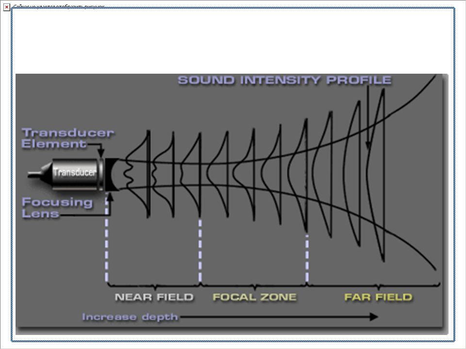
Beam Forming Ultrasound beam can be shaped with lenses Ultrasound transducers (and other antennae) emit energy in three fields –Near field (Fresnel region) –Focused field –Far field (Fraunhofer region)
 emit energy in three fields –Near field (Fresnel region) –Focused field –Far field (Fraunhofer region)")
41
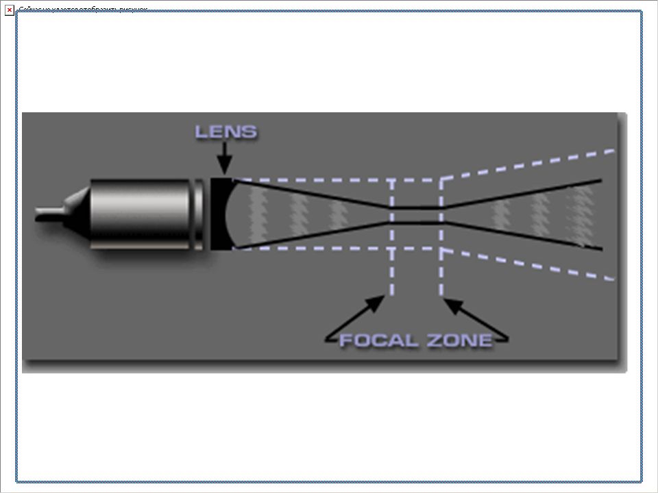
Directing Ultrasound with Lens

44
Beam Focusing A lens will focus the beam to a small spot according to the equation

45
Linear Array

46
Types of Probes

47
Modern Electronic Beam Direction

48
Beam Direction (Listening)
")
49
Wavefronts Add to Form Acoustic Beam

50
Phased Linear Array

51
A-mode Ultrasound Amplitude of reflected signal vs. time

52
A-mode

53
M-mode Ultrasound

54
M-mode

55
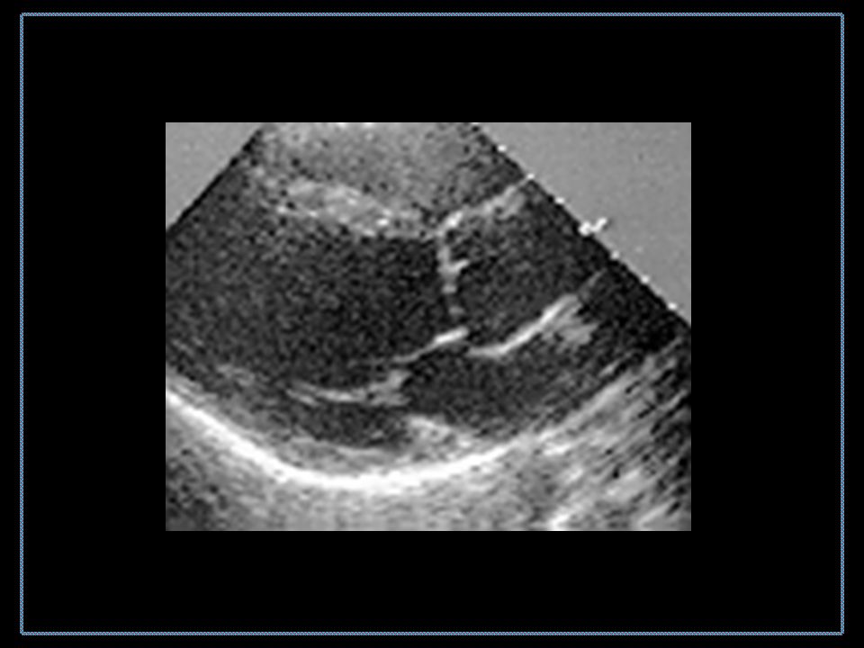
B-mode Ultrasound

56
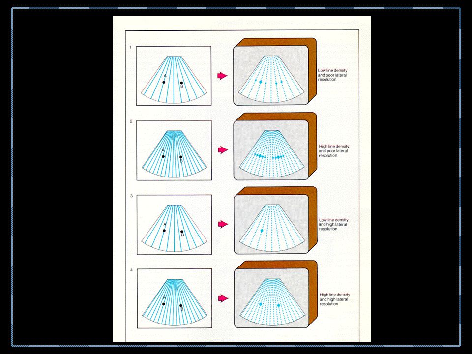
Fan forming

57
B-mode Example

59
Cardiac Ultrasound

60
Standard Sites for Echocardiograms

61
Conventional Cardiac 2D Ultrasound

62
Short-axis Interrogation

63
B-mode Image of Heart

64
Traditional Ultrasound Images End-diastoleEnd-systole

65
B-mode

67
Ventricles

68
Mitral stenosis

69
Results Possible from Echo

70
Geometric problems

72
New developments of Phase-arrays

73
2D Probe Elements

74
Recent 2D array 5Mz 2D array from Stephen Smith’s laboratory, Duke University

75
2D and 3D Ultrasound a. Traditional 2Db, c. New views possible with 3D

76
3D Pyramid of data

77
3D Ultrasound 2D ultrasound transmitter 2D phased array architecture Capture 3D volume of heart 30 volumes per second

78
3D Ultrasound Traditional 2DNew 3D

79
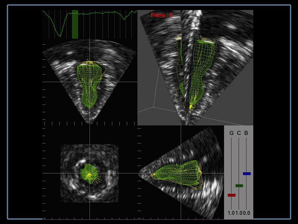
Real-time 3D Ultrasound

82
Velocity of Contraction NormalAbnormal

83
Normal artery

84
Progression of Vascular Disease

85
CAD

86
Severe re-canalization

87
Intravascular Ultrasound (IVUS) Small catheter introduced into artery Catheter transmits and receives acoustic energy Reflected acoustic energy used to build a picture of the inside of the vessel Clinical assessment based on vessel image
 Small catheter introduced into artery Catheter transmits and receives acoustic energy Reflected acoustic energy used to build a picture of the inside of the vessel Clinical assessment based on vessel image")
88
IVUS Catheter 1 - Rotating shaft 2 - Acoustic window 3 - Ultrasound crystal 4 - Rotating beveled acoustic mirror

89
Slightly Diseased Artery in Cross-section Plaque Catheter

90
An array of Images

91
3D IVUS

92
Doppler Principle

93
Doppler

94
Doppler measurements

95
Doppler angle

96
Normal flow

97
Diseased flow

98
Blood Flow Measurements

Similar presentations


 developed during WW II –Sound pulses emitted reflected off metal objects with characteristic.>")


Diagnostic Medical Sonography 2)Sonography3) 4) Vascular Sonography 5)Echocardiography.>")
