Download presentation
Presentation is loading. Please wait.

1
Numerical Simulations of Silverpit Crater Collapse: A Comparison of TEKTON and SALES 2 Gareth Collins, Zibi Turtle, and Jay Melosh LPL, Univ. of Arizona

2
Silverpit ~6 km diameter Central peak: 250 m high 750 m diameter Surrounded by >10 concentric deformation rings 2 - 10 km in diameter Formed in Cretaceous chalk above Jurassic shales 60-65 Ma

3
Silverpit (Stewart and Allen, 2002) (Allen and Stewart, 2003)
 (Allen and Stewart, 2003)")
4
Objectives Understand Silverpit Ring formation Compare 2 modeling techniques to assess: Consistency Limitations Degree to which they are complementary

5
Finite-Element Method Model structure as an assemblage of elements bounded by nodes Specify: Geometry Material properties and rheologies Boundary and initial conditions Construct system of equations: Solve simultaneously for displacements at nodes Calculate stresses using constitutive equations

6
Finite-element Method: Rheology Newtonian Power-law Plastic < c: power-law; ≥ c: Newtonian Exponential T = temperature; R = ideal gas constant; = viscosity; H = activation enthalpy; A, A’, p, n = constants; c = cohesion

7
Finite-element Method: Rheology Elastic Newtonian Power-law Plastic < c: power-law; ≥ c: Newtonian Exponential

8
Finite-element method: Constitutive equations: E = Young’s modulus; = Poisson’s ratio; = viscosity

9
Finite-Element Method Advantages Realistic spatial scales and timescales Simulation of variety of rheologies and geometries Spatial and temporal variation in material properties Reproduce complex structures, including faults Possible to measure credibility of solution Disadvantage Langrangian method, so significant distortion of mesh can lead to numerical instabilities

10
Lagrangian Hydrocode Method Model structure as a regular grid of cells bounded by nodes Specify: Geometry Material properties Boundary and initial conditions Calculate all forces acting on each cell. Assuming forces constant for time step, compute node displacements:

11
Lagrangian Hydrocode: Rheology Elastic Newtonian fluid flow Plastic < Y: elastic; ≥ Y: Newtonian Yield strength Y may be a function of pressure, pressure vibrations, damage and internal energy.

12
Hydrocode Method Advantages Realistic spatial scales and timescales Simulation of variety of rheologies and geometries Spatial and temporal variation in material properties Includes inertia Disadvantage Langrangian method, so significant distortion of mesh can lead to numerical instabilities. No built-in accuracy measure.

13
TEKTON (Finite-Element) Lagrangian Complex rheology Limited strength Faults No inertia Lagrangian Limited rheology Complex strength No faulting Inertia SALES-2 (Hydrocode)
 Lagrangian Complex rheology Limited strength Faults No inertia Lagrangian Limited rheology Complex strength No faulting Inertia SALES-2 (Hydrocode)")
14
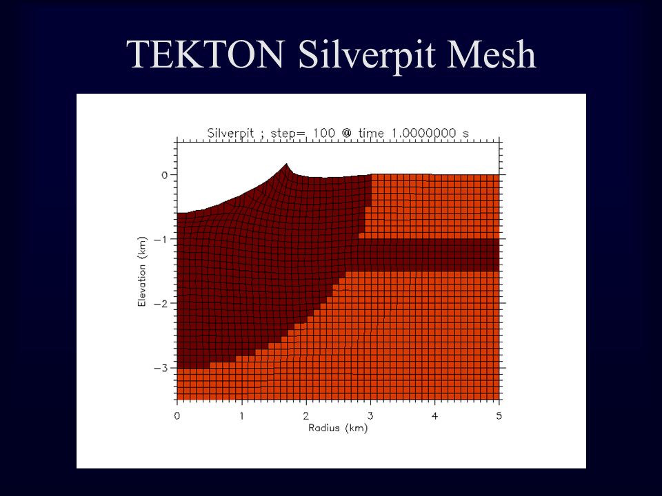
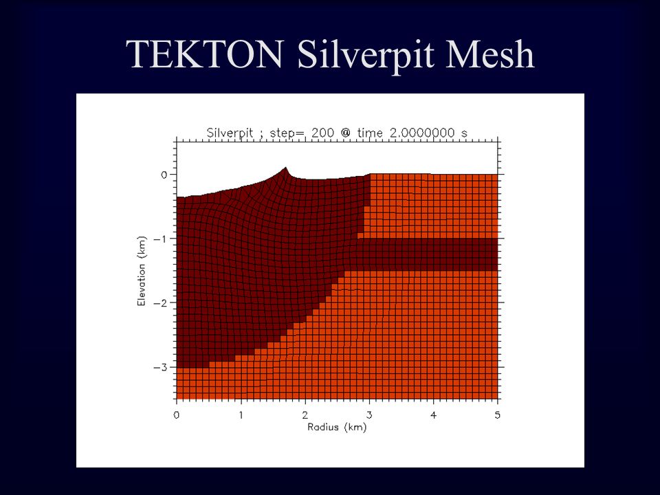
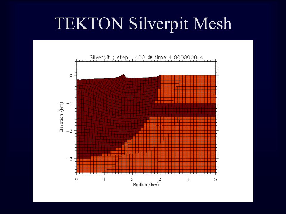
TEKTON Silverpit Mesh Axisymmetric 7 km deep, 12 km wide Elements 100 m x 100 m Boundaries Center and outer: free vertically fixed horizontally Bottom: fixed vertically and horizontally

15
TEKTON Silverpit Mesh

16
Transient crater 3 km diameter Excavated in uniform mesh using the Z-model Simple case: Two materials Low viscosity Newtonian, = 10 7 Pa s Acoustic fluidization Weak layer Power-law, A, Q, n for dolomite (Schmid et al., 1977) Constant density, Young’s modulus, Poisson’s ratio
 Constant density, Young’s modulus, Poisson’s ratio")
17
TEKTON Silverpit Mesh

23
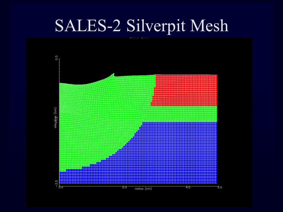
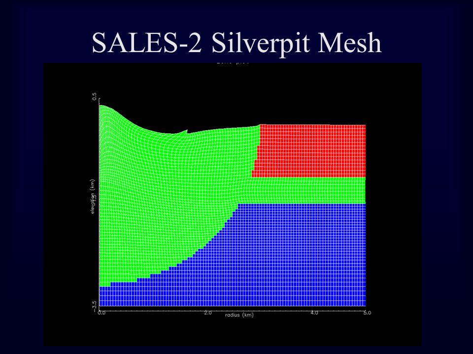
SALES-2 Silverpit Mesh Axisymmetric 4 km deep, 23.6 km wide Elements 50 m x 50 m Boundaries Center: free vertically fixed horizontally Bottom: fixed vertically free horizontally Outer: fixed vertically and horizontally

24
SALES-2 Silverpit Mesh

25
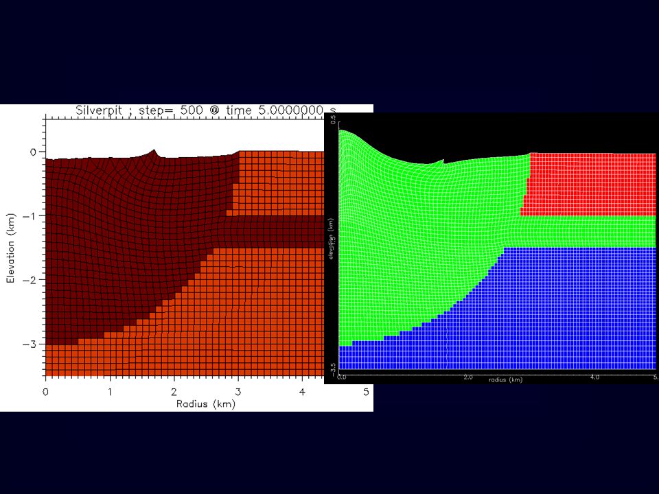
Transient crater 3 km diameter Excavated in uniform mesh using the Z-model Simple case: Two materials Low viscosity Newtonian, = 10 7 Pa s Acoustic fluidization Weak layer Constant density, shear modulus, Poisson’s ratio

26
SALES-2 Silverpit Mesh

32
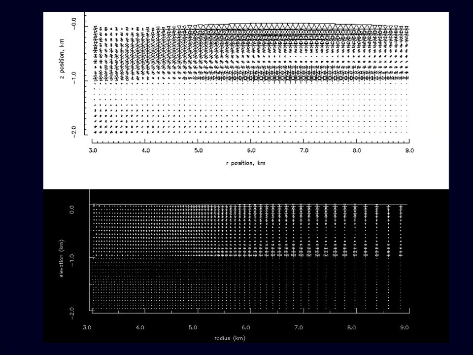
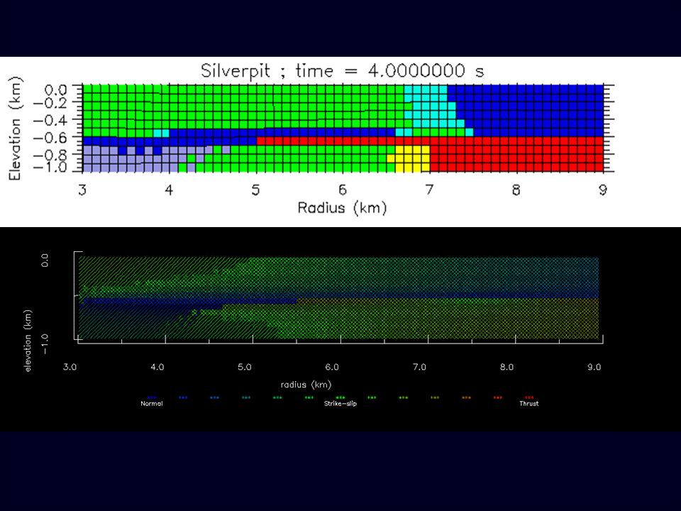
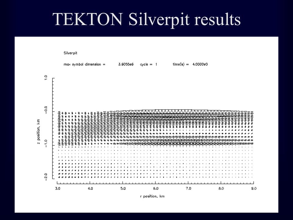
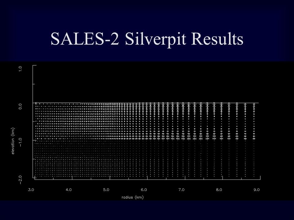
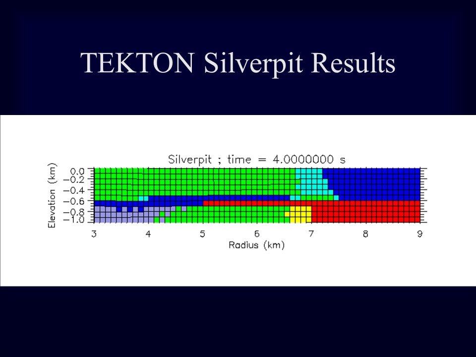
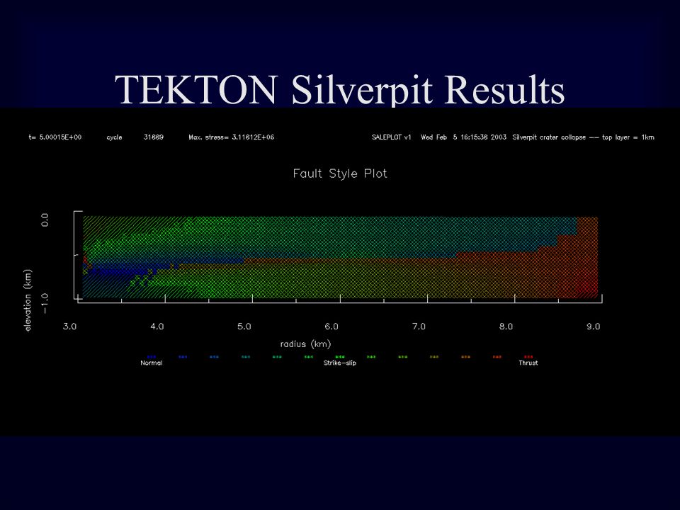
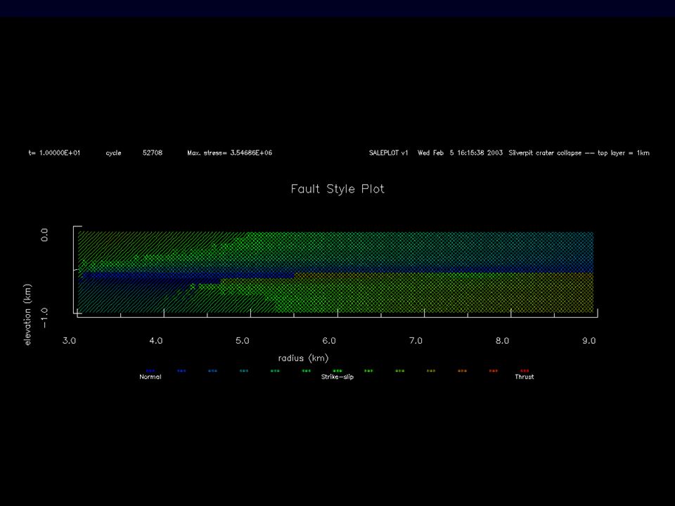
Results Central, near-surface, deformation differs Comparable uplift at depth, few hundred m Timescales for deformation differ Magnitudes and orientations of surface stresses outside of crater are consistent Stress orientations and consequently fault types are broadly consistent with Silverpit observations

33
TEKTON Silverpit results

35
SALES-2 Silverpit Results

37
TEKTON Silverpit Results

Similar presentations


 1. Anderson's Theory of Faulting 2. Rheology (mechanical behavior of rocks) - Elastic: Hooke's.>")


 St. Petersburg Polytechnical University Author:>")

 Simple and complex craters; (b) Fundamental concepts of stress waves, plastic waves, and shock waves; (c)>")


