Download presentation
Presentation is loading. Please wait.

1
Detector studies, Radiation Simulations, Organization FCC Hadron Detector Meeting July 27 th 2015 W. Riegler

2
FCC Week 2016 Rome, 11 – 15 April 2016

3
Document on physics at 100TeV. Including detailed characterization of benchmark channels. Detailed radiation simulations detector technology discussion Detailed tracker studies Baseline magnet system(s) Detailed calorimeter studies … Goals for April 2016 FCC Week
 Detailed calorimeter studies … Goals for April 2016 FCC Week.")
4
Magnet Systems

5
Is a “Standalone Muon System” needed ? Very early LHC detector concepts were based on muon systems only. When trackers were included it was still far from clear whether a tracker close to the IP could survive the high rates and radiation load. The standalone muon system of ATLAS should guarantie that one is on the safe side if trackers ‘would go up in flames on first collisions’. CMS does very much rely on the tracker for the muon performance.

6
Magnet Systems For an FCC hadron detector by 2035, with tracker loads ‘only’ higher by a factor 2-10 with respect to HL-LHC there is no doubt that a tracker can be built that will perform well. We do not see the need for a ‘standalone muon concept’ for an FCC-hh detector. The muon performance can fully rely on the tracker. The ‘CMS like’ detectors with twin solenoid or partially shielded solenoid, together with forward dipoles, should therefore be defined as a baseline magnet system.

7
Coordinate System

8
!! Coordinate Systems !! Y ph X ph Z ph For the LHC detectors, a coordinate system is used where X points towards the inside of the Ring (0,0,0) nominal IP X ph … horizontal towards center of the ring Y ph … perpendicular to X ph and Y ph ‘up’ Z ph … along the beamline, righthanded system This system is different from the one used for beam optics studies as well as FUKA simulations, and in addition it is considered ‘unnatural’. We therefore adopt a different coordinate system for the FCC: FCC Detector Coordinate System: (0,0,0) nominal IP X ph … horizontal towards the outside of the ring Y ph … perpendicular to X ph and Y ph ‘up’ Z ph … clockwise along the beamline, righthanded system Center of the FCC ring
 nominal IP X ph … horizontal towards center of the ring Y ph … perpendicular to X ph and Y ph ‘up’ Z ph … along the beamline, righthanded system This system is different from the one used for beam optics studies as well as FUKA simulations, and in addition it is considered ‘unnatural’. We therefore adopt a different coordinate system for the FCC: FCC Detector Coordinate System: (0,0,0) nominal IP X ph … horizontal towards the outside of the ring Y ph … perpendicular to X ph and Y ph ‘up’ Z ph … clockwise along the beamline, righthanded system Center of the FCC ring.")
9
B Field Map

10
Magnetic Field H. Ten Kate, Matthias Mentink et al. et al. Provided a Field Map [x,0,14],[y,-14,14],[z,0,24]m on a Cartesian grid of 0.25m Y ph X ph Z ph

11
Magnetic Field Y ph X ph Z ph

12
Bz By Magnetic Field

13
Eta = 2.5 Magnetic Field Using this field map we can do semi-analytic studies on detector layout and performance needs in order to arrive at the nominal performance formulated in the DELPHES card.

14
Geometry for Radiation Calculations Past: Very simple estimates for tracker given (W. Riegler) First studies with detailed detector geometry and simplified B-field (C. Young et al.) Next: Detailed detector and magnet geometry with correct B-field. Simulations by Fluka team starting (M. I. Besana, F. Cerutti et al.)
 First studies with detailed detector geometry and simplified B-field (C. Young et al.) Next: Detailed detector and magnet geometry with correct B-field. Simulations by Fluka team starting (M. I. Besana, F. Cerutti et al.).")
15
Beampipe Central pipe: Cylinder Beryllium R in =2cm, R out =2.1cm From z=0 to z=800cm Forward beampipe: Beryllium 1mm wall thickness Projective cone (inner envelope) along 2.5mRad opening angle From z=800cm to z=32000cm Beampipe Connecting to TAS: From z=3200 to 3230cm – cone to go from R=8cm to R=1cm-2cm (matching TAS), Aluminum Between 3230cm and TAS – keep cylindrical beampipe, Aluminum Cylindrical shield around this beampipe will be necessary
 along 2.5mRad opening angle From z=800cm to z=32000cm Beampipe Connecting to TAS: From z=3200 to 3230cm – cone to go from R=8cm to R=1cm-2cm (matching TAS), Aluminum Between 3230cm and TAS – keep cylindrical beampipe, Aluminum Cylindrical shield around this beampipe will be necessary")
16
Beampipe 6.7 6. 5.5 5. 6.5 4.54

17
Coils Coils: Pure Aluminum Z=1010cm, R=625cm Z=1010cm, R=782.5cm Z=760cm, R=1300cm Z=760cm, R=1347.5cm Next Page

18
R=0.182848*Z+41.39 R=0.182848*Z-15.61 Z=1480 Z=2098 X=0.182848*Z+339.39 Rotation around z axis Parallelogram with a given thickness in Y direction Coils: Pure Aluminum

19
Sandwich total 110cm: 10cm Aluminum at 300K 62cm Calomix at 87K 38cm Aluminum at 300K Calomix in Volume (%): LArg 64.8%, Pb 21.7%, Cu 7.2%, Polystyrene 6.3% X 0 of this mix: 2.06cm It will be interesting to change this to W, Cu etc. and see the effect on neutrons and background … ECAL, Liquid Argon Eta 2.5=9.39 degrees Z=2400cm to z=2510m

20
Homegenous material 240cm R in = 360cm, R out = 600cm Material composition in Volume (%): 80% Fe, 20% Polystyrene λ of this mix = 20.5cm HCAL Eta 2.5=9.39 degrees Z=2510cm to z=2750m
: 80% Fe, 20% Polystyrene λ of this mix = 20.5cm HCAL Eta 2.5=9.39 degrees Z=2510cm to z=2750m")
21
Fill entire Volume between coils with Aluminum Since we aim for an air core muon system we assume 1X 0 of material in the 3.6m of space. Since Radiation length of Al is 9cm the Al density has to be scale down by a factor 40. Eta 2.5=9.39 degrees Muon Z=2750cm to z=3150cm

22
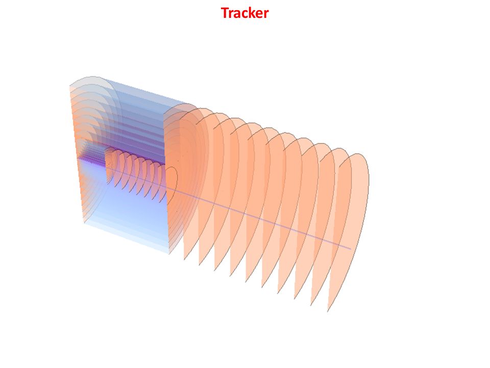
Material composition in Volume (%): Si 20%, C 42%, Cu 2%, Al 6%, Plastic 30% X 0 of this mix: 14.37cm We assume 3% of radiation length per layer, i.e. each layer has a thickness of 0.43cm. Tracker Eta 2.5=9.39 degrees

23
Z0=0Z3=800cm y2=240cm Z1=100cmZ2=300cm Y1=60cm y0=2.2cm IB ID OB OD Inner Barrel (IB) 8+1 Inner Disk (ID) 8 Outer Barrel (OB) 8 Outer Disk (OD) 10 Tracker
 8+1 Inner Disk (ID) 8 Outer Barrel (OB) 8 Outer Disk (OD) 10 Tracker")
24
Inner Barrel: half length (cm), radius (cm) Inner Disks: z (cm), inner radius (cm), outer radius (cm) Outer Barrel: half length (cm), radius (cm) Outer Disks: z (cm), inner radius (cm), outer radius (cm) Tracker
, radius (cm) Inner Disks: z (cm), inner radius (cm), outer radius (cm) Outer Barrel: half length (cm), radius (cm) Outer Disks: z (cm), inner radius (cm), outer radius (cm) Tracker")
26
Eta=0.5 1 1.5 2 2.5 3 3.5 6.7 6. 4 5.5 5. 6.5 4.54 Tracker

27
Eta=0.5 1 1.5 2 2.5 3 3.5 4 Tracker

28
6 discs from z=8m to z=15m with opening angle of eta=2.5. Eta 2.5=9.39 degrees Forward Tracker 6 discs from z=21m to z=24m with opening angle of eta=2.5.

30
Organization

31
There is quite some activity on FCC-hh physics and detector studies. There are quite a few groups doing detector R&D that is targeted towards application in future hadron colliders. We need to get some idea about ‘who does what’ in order to make consistent make consistent progress. The FCC management has put in place an MoU structure to have a formal agreement on FCC activities. MuOs are signed between the FCC management and the participating institutes. The institute representatives form the collaboration board (very similar to the present LHC experiment organization). For the machine studies this process is already very advanced, for the detector studies and physics studies we have to put this in place in the next months. You will hear from us. Organization https://fcc.web.cern.ch/Documents/Organisation/FCC-1502221700-CERN_FCCMoU_Template.docx https://fcc.web.cern.ch/Pages/Organisation.aspx https://fcc.web.cern.ch/Pages/default.aspx
. For the machine studies this process is already very advanced, for the detector studies and physics studies we have to put this in place in the next months. You will hear from us. Organization")
32
Meetings We will try to set the dates for the next FCC hadron detector meetings and physics workshops be throughout the rest of the year a.s.a.p.

Similar presentations


 Project Naba K Mondal Tata Institute, Mumbai, India.>")


, Paul Reimer (ANL) SoLID Collboration Meeting 2013/03.>")


