Download presentation
Presentation is loading. Please wait.

1
Chapter 2 Instruction Addressing and Execution

2
Lesson plan Review some concepts in the first week First assembly program with EMU8086 Related concepts with the first program: –Loading program –Boot process –Handling the stack

3
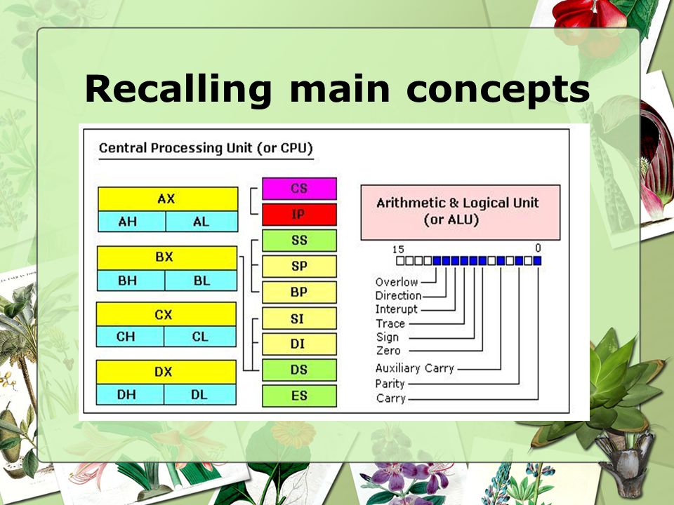
Recalling main concepts

5
Segment: special areas defined to contain CODE, DATA and STACK Paragraph boundary: location evenly divisible by 16 or 10H

6
Recalling main concepts Stack Segment Data Segment Code Segment SS DS CS Segment Registers

7
Practice Start EMU8086 Type the first assembly language given Compile: Compile icon Run:Run icon

8
.model small,.stack.data message db "Hello everybody! I am learning assembly language!","$".code main proc mov ax, seg message mov ds,ax mov ah,09 lea dx,message int 21h mov ax,4c00h int 21h main endp end main

9
Result of the first program

10
Types of programs *.COM and *.EXE files –*.COM: consists of one segment containing code, data and stack –*.exe: separate code, data and stack segments

11
Loading *.exe program Access *.exe from disk 256-byte Program Segment Prefix (PSP) on a paragraph boundary Store the program immediately following the PSP Load address of PSP in the DS & ES Load code segment in CS, set IP Load address of the stack to SS, set SP Transfer control to the program for execution
 on a paragraph boundary Store the program immediately following the PSP Load address of PSP in the DS & ES Load code segment in CS, set IP Load address of the stack to SS, set SP Transfer control to the program for execution")
12
PSP

13
.model small,.stack.data message db "Hello everybody! I am learning assembly language!","$".code main proc mov ax, seg message mov ds,ax mov ah,09 lea dx,message int 21h mov ax,4c00h int 21h main endp end main Assembly directive to define memory model to use in the program

14
Real and Protected mode Real Mode 16-bit Protected Mode 32-bit Protected Mode Segment base address 20-bit 24-bit, from descriptor 32-bit, from descriptor Segment size (limit) 16-bit, 64K bytes (fixed) 16-bit, 1-64K bytes 20-bit, 1-1M bytes or 4K-4G bytes Segment protection noyes Segment register segment base address / 16 selector
 16-bit, 64K bytes (fixed) 16-bit, 1-64K bytes 20-bit, 1-1M bytes or 4K-4G bytes Segment protection noyes Segment register segment base address / 16 selector")
15
Protected mode -Is a type of memory utilization, available on Intel 80286 and later -Support: protection: each program is protected from interference from other programs. extended memory : Enables a single program to access more than 640K of memory. virtual memory : Expands the address space to over 1GB. Multitasking:

16
Booting process What is booting? The process of starting or restarting a computer cold boot Process of turning on a computer after it has been powered off completely warm boot Process of restarting a computer that is already powered on Also called a warm start

17
Booting process processor BIOS hard disk CD-ROM drive (RAM) memory modules CMOS floppy disk drive Step 6 expansion cards How does a personal computer boot up?
 memory modules CMOS floppy disk drive Step 6 expansion cards How does a personal computer boot up")
18
BIOS Boot process BIOS routine FFFF0H Interrupt Vector Table BIOS Data Areas Access the bootstrap loader Check ports Initialize devices

19
.model small,.stack.data message db "Hello everybody! I am learning assembly language!","$".code main proc mov ax, seg message mov ds,ax mov ah,09 lea dx,message int 21h mov ax,4c00h int 21h main endp end main Assembly directive to define stack to use in the program

20
STACK The word is from data structure Last In, First Out (LIFO) mechanism STACK in OS has three main functions: –Contains return address –Data –Content of present registers
 mechanism STACK in OS has three main functions: –Contains return address –Data –Content of present registers")
21
STACK PUSH –Decrease SP by 2 and store a value there POP –Return a value from stack and increase SP by 2

22
Lesson plan Review loading an *.exe file Concept of execution of instructions Practice: Execution of instructions

23
Access *.exe from disk 256-byte Program Segment Prefix (PSP) on a paragraph boundary Store the program immediately following the PSP Load address of PSP in the DS & ES Load code segment in CS, set IP Load address of the stack to SS, set SP Transfer control to the program for execution Loading *.exe file
 on a paragraph boundary Store the program immediately following the PSP Load address of PSP in the DS & ES Load code segment in CS, set IP Load address of the stack to SS, set SP Transfer control to the program for execution Loading *.exe file")
24
The sequence of segments (code, data, and stack) is given SS: contains the address of the beginning of the stack CS: contains the address of the beginning of the code segment DS: contains the address of the beginning of the data segment SP: contains the size of stack
 is given SS: contains the address of the beginning of the stack CS: contains the address of the beginning of the code segment DS: contains the address of the beginning of the data segment SP: contains the size of stack")
25
Practice 2B360H PSP Stack Segment Data Segment Code Segment Memory

26
Practice 2B360H PSP Stack Segment Data Segment Code Segment Memory PSP 2B360H PSP size 100H Offset 0H SS 2B460H (stored as 2B46) 2B46H SS
 2B46H SS")
27
Practice 2B360H PSP Stack Segment Data Segment Code Segment Memory 2B46H SS PSP 2B360H PSP size 100H Offset 30H 70H CS 2B500H (stored as 2B50) CS 2B50H
 CS 2B50H")
28
Practice 2B360H PSP Stack Segment Data Segment Code Segment Memory 2B46H SS CS 2B50H 2B36H DS ES SP 0030H

29
Instruction Execution and Addressing Executing an instruction include –Fetch the next instruction, put to a queue (QUEUE: FIFO vs. STACK LIFO) –Decode the instruction –Execute the instruction
 –Decode the instruction –Execute the instruction.")
30
Example 4AF0 CS 0013 IP 4AF13H CS segment address: 4AF00H IP offset: 0013H ________________________ + Instruction address: 04B1 DS

31
Example 4AF0 CS 0013 IP 4AF13H A01200 Memory 04B1 DS Decode instruction: AO: MOV [0012] to AL
![Example 4AF0 CS 0013 IP 4AF13H A01200 Memory 04B1 DS Decode instruction: AO: MOV [0012] to AL](http://images.slideplayer.com/25/7967136/slides/slide_31.jpg "Example 4AF0 CS 0013 IP 4AF13H A01200 Memory 04B1 DS Decode instruction: AO: MOV [0012] to AL")
32
Example 4AF0 CS 0013 IP 04B03H A01200 Memory 04B1 DS DS segment address:04B10H IP offset: 0012H ________________________ + Data address: 04B22H

33
Example 4AF0 CS 0013 IP 04B03H A01200 1B Memory 04B1 DS 04B22 Data address: 04B22H | 1B AX AHAL

34
Practice Viewing memory location using DEBUG At DOS prompt, type: DEBUG Checking Serial and parallel port: D 40:00 Checking system equipment D 40:10

35
Practice Viewing memory location using DEBUG At DOS prompt, type: DEBUG Checking Serial and parallel port: D 40:00 Checking system equipment D 40:10

36
Practice Viewing memory location using DEBUG At DOS prompt, type: DEBUG Checking Serial and parallel port: D 40:00 Checking system equipment D 40:10 22 C8C822 reverse Number of parallel printer ports=11(binary)=3 (15,14) Number of serial ports=100(binary)=4 (11-9) Number of diskette devices=00(binary)=1 (7,6) Initial video mode =10 (5,4) (80x25 color) Coprocessor present: 1 (1) Diskette drive is present: 0 (0)
=3 (15,14) Number of serial ports=100(binary)=4 (11-9) Number of diskette devices=00(binary)=1 (7,6) Initial video mode =10 (5,4) (80x25 color) Coprocessor present: 1 (1) Diskette drive is present: 0 (0)")
37
Checking the keyboard status –D 40:17 (With Numlock and Caplock) Checking video status –D 40:49 –D 40:84 Practice (cont.)
 Checking video status –D 40:49 –D 40:84 Practice (cont.)")
38
Checking copyright notice & serial number –D FE00:0 Checking ROM BIOS date D FFFF:5 Practice (cont.)
")
39
Running the first assembly program step by step using EMU 8086 Practice (cont.)
")
Similar presentations


. Practice Modify the program to get a string from a keyboard to display the input string on the middle of the screen with reverse.>")


>")


 Microprocessor.>")
 Procedures Procedure Parameters Software Interrupts MS-DOS.>")


 4 GB addressable RAM –(00000000 to FFFFFFFFh) Each program assigned a memory partition which is protected from.>")

>")