Download presentation
Presentation is loading. Please wait.

1
The MIPS R10000 Superscalar Microprocessor Kenneth C. Yeager Nishanth Haranahalli February 11, 2004

2
A superscalar processor is one that can fetch, execute an complete more than one instruction in parallel. The Microprocessor without Interlocked Pipeline Stages R10000 superscalar processor fetches and decodes four instructions per cycle and issues them to five-fully pipelined low latency execution units. The Instructions are fetched and executed speculatively beyond branches.

3
Features The R10000 processor is a single-chip superscalar RISC processor that fetches & decodes four instructions per cycle, appending them to one of three instruction queues Speculatively executes beyond branches, with a four-entry branch stack. Dynamic Execution Scheduling and out-of-order execution. implements the 64-bit MIPS IV instruction set architecture. it uses a precise exception model (exceptions can be traced back to the instruction that caused them) Five independent pipelined executions include nonblocking load/store unit Two 64-bit integer ALU’s Floating point adder Floating point multiplier Floating point divide & square root The hierarchical, non-blocking memory subsystem includes Separate on-chip 32-Kbyte primary instruction and data caches External secondary cache and System interface ports 64-bit multiprocessor system interface
 Five independent pipelined executions include nonblocking load/store unit Two 64-bit integer ALU’s Floating point adder Floating point multiplier Floating point divide & square root The hierarchical, non-blocking memory subsystem includes Separate on-chip 32-Kbyte primary instruction and data caches External secondary cache and System interface ports 64-bit multiprocessor system interface.")
4
Previous MIPS processors had linear pipeline architectures; an example of such a linear pipeline is the R4400 pipeline. In R4400 pipeline architecture, an instruction is executed each cycle of the pipeline clock. The structure of 4-way superscalar pipeline At each stage, four instructions are handled in parallel.

5
Design Rationale R10000 implements register mapping & nonblocking caches. If an instruction misses the cache, it must wait until the operand to be refilled, but other instructions can continue out of order. This reduces effective latency, because refills begin early and up to four refills proceed in parallel. R10000 design includes complex hardware that dynamically reorders instruction execution based on operand availability. The processor looks ahead up to 32 instructions to find possible parallelism. This window is large enough to hide memory refills from secondary cache.

6
Hardware Implementation 0.35um CMOS technology 16.64 X 17.934 mm chip 298 mm 2 6.8 million transistors

7
Stage 1 - Fetching Stage 2 - Decoding Stage 3 - Issuing Instructions Stage 4 - Stage 6 execution stage Integer - one stage Load - two stage Floating-point - three stage Writes results into the register file - first half of the next stage Stage 7 - Storing Results Operation overview

8
Instruction fetch Instruction fetching is the process of reading instructions from the instruction cache. The Processor fetches four instructions in parallel at any word alignment within 16-word instruction cache line. R10000 fetches unaligned instructions using separate select signal for each instruction. These instructions rotate If necessary, so that they are decoded in order.

9
Branch Unit Prediction (fetches instructions speculatively along predicted path) 2-bit algorithm based on a 512-entry branch history table 87% prediction accuracy for Spec92 integer programs Branch stack When it decodes a branch, the processor saves its state in a four-entry branch stack Contains Alternate branch address complete copies of the integer and floating-point map tables, control bits Branch verification - If the prediction was incorrect The processor immediately aborts all instructions fetched along the mis-predicted path and restores its state from the branch stack
 2-bit algorithm based on a 512-entry branch history table 87% prediction accuracy for Spec92 integer programs Branch stack When it decodes a branch, the processor saves its state in a four-entry branch stack Contains Alternate branch address complete copies of the integer and floating-point map tables, control bits Branch verification - If the prediction was incorrect The processor immediately aborts all instructions fetched along the mis-predicted path and restores its state from the branch stack")
10
Instruction Decode Decodes and maps four instructions in parallel during stage 2 and writes them into the appropriate instruction queue. –Stops if the active list or a queue becomes full Few decode instructions depend on type of instructions being decoded. Instructions that modify/read control registers are executed serially.

11
Register Renaming Register renaming is used to resolve register dependencies during the dynamic execution of instructions. It determines memory address dependencies in the address queue. Each time a new value is put in a logical register, it is assigned to a new physical register. Each physical register has only a single value. Dependencies are determined using these physical register numbers. Register map tables –Integer – 33X6 bit RAM (r1 – r31, Hi and Lo) –Floating-point – 32X6 bit RAM (f0 – f31) –5-bit logical to 6-bit physical address mapping Free lists –Lists of currently unassigned physical registers –32 entry circular FIFO four parallel, eight-deep
 –Floating-point – 32X6 bit RAM (f0 – f31) –5-bit logical to 6-bit physical address mapping Free lists –Lists of currently unassigned physical registers –32 entry circular FIFO four parallel, eight-deep.")
12
Active list All instructions currently active in the machine kept in 32 entry FIFO four parallel, eight-deep Provides unique 5-bit tag for each instruction When execution unit completes an instruction, it sends its tag to the active list, which sets the done bit. Logical destination number Old physical register number When an exception occurs, subsequent instructions never graduate. Processor restores old mappings from the active list. Busy-bit tables For each physical register (integer and floating-point) 64X1 bit multiport RAM Indicate whether the register currently contains a valid value. The bit is set when the corresponding register leaves the free list. Resets the bit when execution unit writes a value into the register.
 64X1 bit multiport RAM Indicate whether the register currently contains a valid value. The bit is set when the corresponding register leaves the free list. Resets the bit when execution unit writes a value into the register..")
13
Instruction Queues Each instruction decoded in stage 2 is appended to one of the three instruction queues. integer queue (the integer queue issues instructions to the two integer ALU pipelines) address queue (the address queue issues one instruction to the Load/Store Unit pipeline) floating-point queue (the floating-point queue issues instructions to the floating-point adder and multiplier pipelines)
 address queue (the address queue issues one instruction to the Load/Store Unit pipeline) floating-point queue (the floating-point queue issues instructions to the floating-point adder and multiplier pipelines).")
14
Integer Queue The integer queue issues instructions to the two integer arithmetic units: ALU1 and ALU2. The integer queue contains 16 instruction entries. Up to four instructions may be written during each cycle. The queue releases the entry as soon as it issues the instruction to an ALU. Branch and shift instructions can be issued only to ALU1. Integer multiply and divide instructions can be issued only to ALU2. Other integer instructions can be issued to either ALU. Integer queue contains three operand select fields; which contain physical register numbers. Each field contains a ready bit, initialized from busy bit table. The queue compares each select with the three destination selects corresponding to write ports in the integer register file. The queue issues the function code and immediate values to the execution units. The branch mask determines if the instruction aborted because of a mispredicted branch.

15
Floating point Queue The floating-point queue issues instructions to the floating-point multiplier and the floating-point adder. The floating-point queue contains 16 instruction entries. Up to four instructions may be written during each cycle; newly-decoded floating-point instructions are written into empty entries in random order. Instructions remain in this queue only until they have been issued to a floating-point execution unit. Floating point loads have three-cycle latency.

16
Address Queue The address queue issues instructions to the load/store unit. The address queue contains more complex control logic than the other queues. The address queue contains 16 instruction entries. Unlike the other two queues, the address queue is organized as a circular First-In First-Out (FIFO) buffer. The decoded load/store instruction is written into the next available sequential empty entry; up to four instructions may be written during each cycle and removes the entry after that instruction graduates. The queue uses instruction order to determine memory dependencies and to give priority to the oldest instruction. The FIFO order maintains the program’s original instruction sequence so that memory address dependencies may be easily computed. Instructions remain in this queue until they have graduated; they cannot be deleted immediately after being issued, since the load/store unit may not be able to complete the operation immediately. When the processor restores a mispredicted branch, the address queue removes all instructions decoded after that branch from the end. Store instructions require special coordination between the address queue and active list. The queue must write data cache precisely when store instruction graduates.
 buffer. The decoded load/store instruction is written into the next available sequential empty entry; up to four instructions may be written during each cycle and removes the entry after that instruction graduates. The queue uses instruction order to determine memory dependencies and to give priority to the oldest instruction. The FIFO order maintains the program’s original instruction sequence so that memory address dependencies may be easily computed. Instructions remain in this queue until they have graduated; they cannot be deleted immediately after being issued, since the load/store unit may not be able to complete the operation immediately. When the processor restores a mispredicted branch, the address queue removes all instructions decoded after that branch from the end. Store instructions require special coordination between the address queue and active list. The queue must write data cache precisely when store instruction graduates..")
17
Register Files Integer register files –64 registers –7 read ports –3 write ports Floating-point register file –64 registers –5 read ports –3 write ports Execution units read operands directly from the register files and write results directly back. A separate 64word*1bit condition file indicates if the value in the corresponding physical register is non-zero.

18
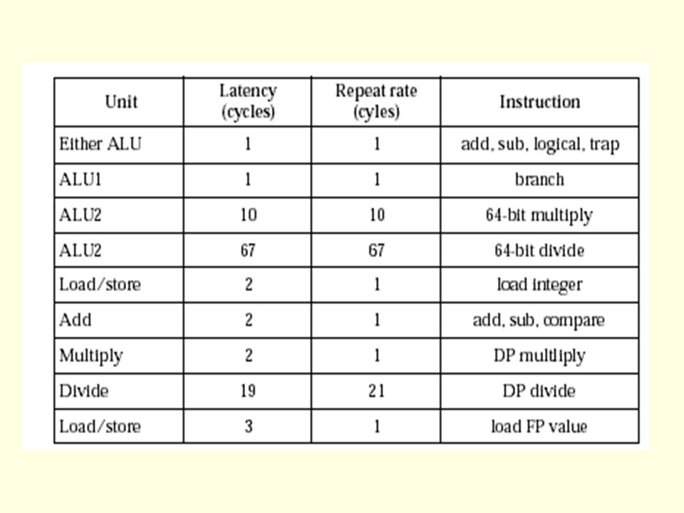
Functional Units The five execution pipelines allow overlapped instruction execution by issuing instructions to the following five functional units: two integer ALUs (ALU1 and ALU2) the Load/Store unit (address calculate) the floating-point adder the floating-point multiplier Integer multiply and divide operations are performed by an Integer Multiply/Divide execution unit; these instructions are issued to ALU2. ALU2 remains busy for the duration of the divide. Floating-point divides are performed by the Divide execution unit; these instructions are issued to the floating-point multiplier. Floating-point square root are performed by the Square-root execution unit; these instructions are issued to the floating-point multiplier.

19
Integer ALU ’ s During each cycle, the integer queue can issue two instructions to the integer execution units Each of the two integer ALUs contains a 64-bit adder and a logic unit. In addition, ALU 1 - 64-bit shifter and branch condition logic ALU 2 – a partial integer multiplier array and integer-divide logic Integer multiplication and division Hi and Lo registers Multiplication – double-precision product Division – remainder and quotient Algorithm Multiplication – Booth’s algorithm Division – nonrestoring algorithm

20
Floating-point execution units All floating-point operations are issued form the floating-point queue Values are packed in IEEE std 754 single or double precision formats in the floating-point register file –Operands are unpacked as they are read and results are packed before they are written back. It has a 64-bit parallel multiply unit which also performs move instructions. it has a 64-bit add unit which handles addition, subtraction, and miscellaneous floating-point operations it has separate 64-bit divide and square-root units which can operate concurrently. Algorithm Multiplication – Booth’s Divide & Square root – SRT algorithm

22
Memory Hierarchy To run large programs effectively, the R10000 implements a non- blocking memory hierarchy with two levels of caches. Memory address Translation. - It has a 44-bit virtual address calculation unit. - Converts 44-bit virtual address to 40-bit Physical address. - It has a 64-entry Translation-Lookaside Buffer (TLB). Address Calculation. The R10000 calculates virtual memory address as the sum of two. 64-bit registers or sum of a register and a 16-bit immediate field.
. Address Calculation. The R10000 calculates virtual memory address as the sum of two. 64-bit registers or sum of a register and a 16-bit immediate field..")
23
Primary Instruction Cache (I-cache) It contains 32 Kbytes It reads four consecutive instructions per cycle, beginning on any word boundary within a cache block, but cannot fetch across a block boundary. Its instructions are predecoded, appended with 4-bit execution identification bits. Primary Data Cache (D-cache) It has two interleaved arrays (two 16 Kbyte banks) It contains 32 Kbytes It handles 64-bit load/store operations It handles 128-bit refill or write-back operations It permits non-blocking loads and stores. Secondary cache 128 b wide interface 512KB–16 MB
 It has two interleaved arrays (two 16 Kbyte banks) It contains 32 Kbytes It handles 64-bit load/store operations It handles 128-bit refill or write-back operations It permits non-blocking loads and stores. Secondary cache 128 b wide interface 512KB–16 MB.")
24
System interface 64-bit split-transaction system bus with multiplexed address and data Up to four R10000 chips can directly connected a cluster Overlaps up to eight read request Substantial resources are allocated to support concurrency and oit-of-order operation. Eight entry cluster buffer tracks all outstanding operations on the system bus. Clock Pipeline clock – 200 MHz System interface bus - 50 ~ 200MHz Secondary cache – 66.7 ~ 200MHz Test features Observes internal signal with ten 128-bit linear-feedback shift registers

25
System Configuration

26
Summary MIPS R10000 is Dynamic, superscalar RISC processor Fetches/decodes four instructions per cycle Speculatively executes Dynamic out-of-order execution Register renaming using map table Future Work Pipelines operating at faster clock rates Latency reduction To Split Integer Multiplication & division as separate blocks To reduce the repeat cycle rate.

Similar presentations


 Hardware data structures retirement register file (RRF) (~ IBM 360/91 physical registers)>")


>")
 1 Computer Architecture Out-of-order execution By Dan Tsafrir, 11/4/2011 Presentation based.>")


