Download presentation
Presentation is loading. Please wait.

1
LCD Interfacing

2
Introduction to LCD LCD (Liquid Crystal Display) screen is an electronic display module and find a wide range of applications. A 16x2 LCD display is very basic module and is very commonly used in various devices and circuits. 16 Characters x 2 Lines Built-in HD44780 Equivalent LCD Controller
 screen is an electronic display module and find a wide range of applications. A 16x2 LCD display is very basic module and is very commonly used in various devices and circuits. 16 Characters x 2 Lines. Built-in HD44780 Equivalent LCD Controller.")
3
Liquid Crystal Display (LCD)
PINS

4
Pin Configuration

5
Fixed voltage pins: Pin1 (Vss/Gnd), Pin2(Vcc), Pin3(Vee, connected to a port) are dc lines, they are directly connected to voltage sources and to ground, they are not controlled by the microcontroller. Control Pins: Pin4(RS), Pin(R/W), Pin6(EN) are control pins Backlight Control Pins: There are two extra pins (LED+ and LED-) to turn on the backlight of LCD display. Data Pins: Pin7 to Pin14 are data pins.
, Pin2(Vcc), Pin3(Vee, connected to a port) are dc lines, they are directly connected to voltage sources and to ground, they are not controlled by the microcontroller. Control Pins: Pin4(RS), Pin(R/W), Pin6(EN) are control pins. Backlight Control Pins: There are two extra pins (LED+ and LED-) to turn on the backlight of LCD display. Data Pins: Pin7 to Pin14 are data pins.")
6
CONTROL PINS RS is the register select pin. To write display data to the LCD (characters), this pin has to be high. For commands his pin needs to be low. R/W is the data direction pin. For WRITING data TO the LCD it has to be low, for READING data FROM the LCD it has to be high. E is the Enable pin. When writing data to the LCD, the LCD will read the data on the falling edge of E
, this pin has to be high. For commands his pin needs to be low. R/W is the data direction pin. For WRITING data TO the LCD it has to be low, for READING data FROM the LCD it has to be high. E is the Enable pin. When writing data to the LCD, the LCD will read the data on the falling edge of E.")
7
LCD use in 4 bit mode & Masking
The Data or command is sent in nibble form (1 nibble= 4 bit) in the 4-bit mode. The higher nibble is sent first followed by the lower nibble. The function of RS, RW and EN pins remains similar to 8-bit mode. Higher pins of PORTX (PX4-PX7) are connected to data line. So, the higher nibble of a byte can be sent to LCD data lines by masking lower nibble. To send lower nibble, data byte is shifted left for four places. Lower nibble replaces higher nibble by this shifting. Data is sent after masking the byte. Example: if data is 0x32; 0x20 (Masking) 0xF0 resultant data is sent to LCD
 in the 4-bit mode. The higher nibble is sent first followed by the lower nibble. The function of RS, RW and EN pins remains similar to 8-bit mode. Higher pins of PORTX (PX4-PX7) are connected to data line. So, the higher nibble of a byte can be sent to LCD data lines by masking lower nibble. To send lower nibble, data byte is shifted left for four places. Lower nibble replaces higher nibble by this shifting. Data is sent after masking the byte. Example: if data is x32; x20. (Masking) xF0. resultant data is sent to LCD.")
8
Save the new file with .c extension

9
Open Make File from start->programs-> winavr

10
Enable Editing MakeFile (last option from drop down menu)
")
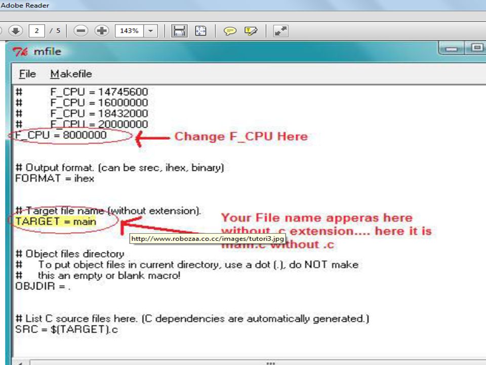
11
Click MakeFile (from menu) -> main file name -> give the same name as above without .c extension. As for the above example name it as LCD -> Click OK Now scroll a little above to the section F_CPU = > Make the desired change be editing it. If you are using a 16MHz crystal then F_CPU should be equal to

13
Click MakeFile (from menu) -> MCU type -> ATmega -> atmega16 (If you are using ATmega16).
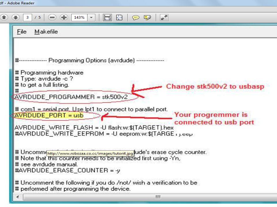
Click MakeFile (from menu) -> Port -> USB (if you are using a usb type of programmer) else choose the COM port where you have connected the programmer. Scroll to the section AVRDUDE_PROGRAMMER = stk500v2. Change stk500v2 by usbasp(or usbtiny) if you are using a USBasp programmer. It is the most commonly used programmer. Hence it looks like AVRDUDE_PROGRAMMER = usbasp (or usbtiny)
 -> Port -> USB (if you are using a usb type of programmer) else choose the COM port where you have connected the programmer. Scroll to the section AVRDUDE_PROGRAMMER = stk500v2. Change stk500v2 by usbasp(or usbtiny) if you are using a USBasp programmer. It is the most commonly used programmer. Hence it looks like AVRDUDE_PROGRAMMER = usbasp (or usbtiny)")
15
Click MakeFile (from menu) -> Programmer (if you are NOT using a USBasp programmer) and choose your programmer. Now the last step -> file -> save as -> browse to the folder where you have saved the file led.c (Desktop/AVR/led_blink) then save it. Make sure the file name is not changed, it should be named as Makefile Now you are all done to write your code in programmer’s notepad and compile it and even burn it to your MCU with the help of WinAVR.
 then save it. Make sure the file name is not changed, it should be named as Makefile. Now you are all done to write your code in programmer’s notepad and compile it and even burn it to your MCU with the help of WinAVR.")
16
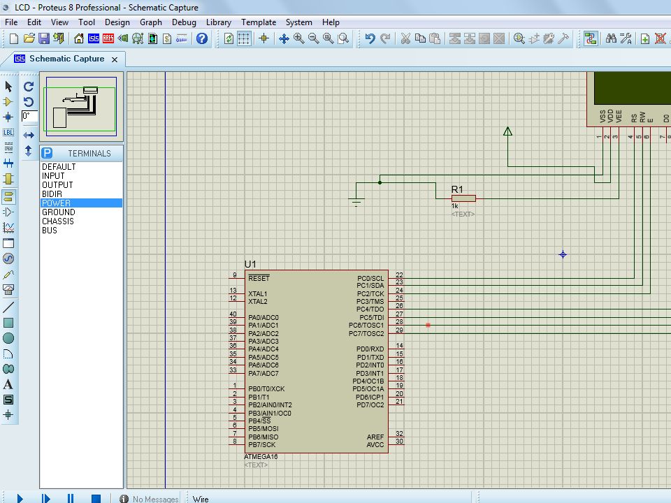
Proteus Simulation

17
Click here

18
Write name and path of new project

19
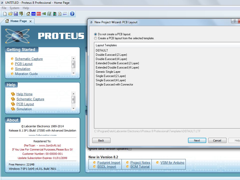
Create DEFAULT Schematic capture

22
Click on “P” to pick components
New Project Zoom IN/OUT Click on “P” to pick components Power/Ground Click to run simulation

23
Search Box Select Atmega 16 Click Ok

24
In similar manner we can select other devices

25
Select 16*2 alphanumeric LCD

27
LCD functions for Win AVR
LCDInit(uint8_t style); LCDWriteString(‘msg’); LCDWriteInt(int val,unsigned int field_length); LCDGotoXY(uint8_t x,uint8_t y); LCDClear() LCDData(‘w’)
; LCDWriteString(‘msg’); LCDWriteInt(int val,unsigned int field_length); LCDGotoXY(uint8_t x,uint8_t y); LCDClear() LCDData(‘w’)")
28
LCD in WINAVR #include <avr/io.h> #include <util/delay.h>
#include "lcd.h" #include "lcd.c" #include "custom_char.h" void main() {DDRC=0xff; LCDInit(LS_BLINK); while(1) {LCDGotoXY(5,0); LCDWriteString("ZAINAB"); LCDGotoXY(4,1); LCDWriteInt(123); } LCD in WINAVR
 {DDRC=0xff; LCDInit(LS_BLINK); while(1) {LCDGotoXY(5,0); LCDWriteString( ZAINAB ); LCDGotoXY(4,1); LCDWriteInt(123); } LCD in WINAVR.")
Similar presentations


 2. Programmable.>")


