Download presentation
Presentation is loading. Please wait.

6
The V I Relationship for a Resistor Let the current through the resistor be a sinusoidal given as Is also sinusoidal with amplitude amplitudeAnd phase The sinusoidal voltage and current in a resistor are in phase

7
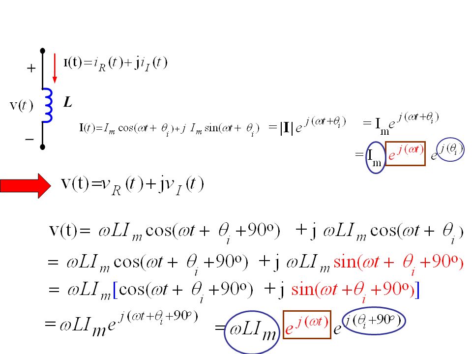
The V I Relationship for an Inductor Let the current through the resistor be a sinusoidal given as The sinusoidal voltage and current in an inductor are out of phase by 90 o The voltage lead the current by 90 o or the current lagging the voltage by 90 o Now we rewrite the sin function as a cosine function

8
The V I Relationship for a Capacitor Let the voltage across the capacitor be a sinusoidal given as The sinusoidal voltage and current in an inductor are out of phase by 90 o The voltage lag the current by 90 o or the current leading the voltage by 90 o Now we rewrite the sin function as a cosine function

9
The Sinusoidal Response KVL This is first order differential equations which has the following solution We notice that the solution is also sinusoidal of the same frequency However they differ inamplitudeandphase

10
Complex Numbers Rectangular Representation

11
Complex Numbers (Polar form) Rectangular Representation
 Rectangular Representation")
12
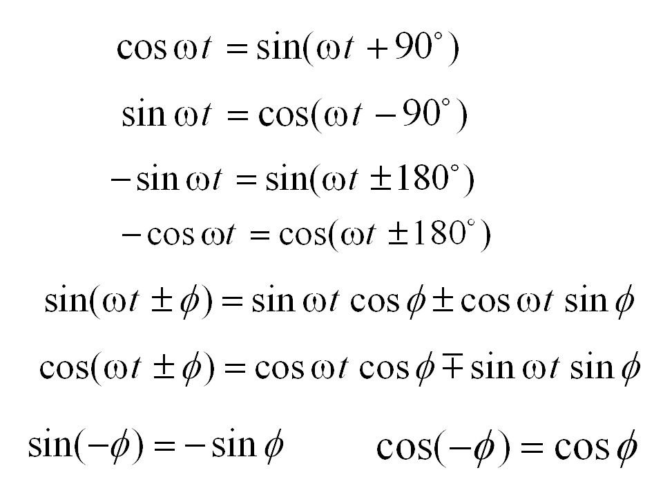
Euler’s Identity Euler’s identity relates the complex exponential function to the trigonometric function Adding Subtracting

13
Euler’s Identity The left side is complex functionThe right side is complex function The left side is real functionThe right side is real function

14
Complex Numbers (Polar form) Rectangular Representation Short notation
 Rectangular Representation Short notation")
15
Rectangular Representation OR Polar Representation Real Numbers

16
Rectangular Representation OR Polar Representation

17
Rectangular Representation Imaginary Numbers Polar Representation OR

18
Rectangular Representation OR Polar Representation

19
Complex Conjugate Complex Conjugate is defined as

20
Complex Numbers (Addition)
")
21
Complex Numbers (Subtraction)
")
22
Complex Numbers (Multiplication) Multiplication in Rectangular Form Multiplication in Polar Form Multiplication in Polar Form is easier than in Rectangular form
 Multiplication in Rectangular Form Multiplication in Polar Form Multiplication in Polar Form is easier than in Rectangular form")
23
Complex Numbers (Division) Division in Rectangular Form
 Division in Rectangular Form")
24
Complex Numbers (Division) Division in Polar Form Division in Polar Form is easier than in Rectangular form
 Division in Polar Form Division in Polar Form is easier than in Rectangular form")
25
Complex Conjugate Identities ( can be proven) OR Other Complex Conjugate Identities ( can be proven)
 OR Other Complex Conjugate Identities ( can be proven)")
26
Let the current through the indictor be a sinusoidal given as Let the current through the indictor be a sinusoidal given as From Linearity ifthen

27
The solution which was found earlier

28
The V I Relationship for an Inductor Let the current through the resistor be a sinusoidal given as The sinusoidal voltage and current in an inductor are out of phase by 90 o The voltage lead the current by 90 o or the current lagging the voltage by 90 o Now we rewrite the sin function as a cosine function

29
From Linearity if The solution which was found earlier

30
The solution is the real part of This will bring us to the PHASOR method in solving sinusoidal excitation of linear circuit

32
Phasor Now if you pass a complex current You get a complex voltage The real part is the solution

33
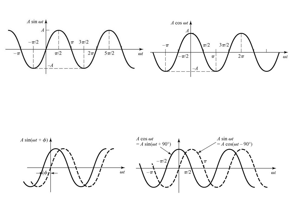
The phasor The phasor is a complex number that carries the amplitude and phase angle information of a sinusoidal function The phasor concept is rooted in Euler’s identity We can think of the cosine function as the real part of the complex exponential and the sine function as the imaginary part Because we are going to use the cosine function on analyzing the sinusoidal steady-state we can apply

34
Phasor Transform Were the notation Is read “ the phasor transform of Moving the coefficient V m inside

35
The V I Relationship for a Resistor Let the current through the resistor be a sinusoidal given as Is also sinusoidal with amplitude amplitudeAnd phase The sinusoidal voltage and current in a resistor are in phase

36
Now let us see the pharos domain representation or pharos transform of the current and voltage Which is Ohm’s law on the phasor ( or complex ) domain and
 domain and")
37
The voltage and the current are in phase Real Imaginary

38
The V I Relationship for an Inductor Let the current through the resistor be a sinusoidal given as The sinusoidal voltage and current in an inductor are out of phase by 90 o The voltage lead the current by 90 o or the current lagging the voltage by 90 o You can express the voltage leading the current by T/4 or 1/4f seconds were T is the period and f is the frequency

39
Now we rewrite the sin function as a cosine function ( remember the phasor is defined in terms of a cosine function) The pharos representation or transform of the current and voltage But since Therefore and
 The pharos representation or transform of the current and voltage But since Therefore and")
40
The voltage lead the current by 90 o or the current lagging the voltage by 90 o Real Imaginary

41
The V I Relationship for a Capacitor Let the voltage across the capacitor be a sinusoidal given as The sinusoidal voltage and current in an inductor are out of phase by 90 o The voltage lag the current by 90 o or the current leading the voltage by 90 o

42
The V I Relationship for a Capacitor The pharos representation or transform of the voltage and current and

43
The voltage lag the current by 90 o or the current lead the voltage by 90 o Real Imaginary

44
Time-Domain Phasor ( Complex or Frequency) Domain
 Domain")
45
Impedance and Reactance The relation between the voltage and current on the phasor domain (complex or frequency) for the three elements R, L, and C we have When we compare the relation between the voltage and current, we note that they are all of form: Which the state that the phasor voltage is some complex constant ( Z ) times the phasor current This resemble ( شبه ) Ohm’s law were the complex constant ( Z ) is called “Impedance” (أعاقه ) Recall on Ohm’s law previously defined, the proportionality content R was real and called “Resistant” (مقاومه ) Solving for ( Z ) we have The Impedance of a resistor is The Impedance of an indictor is The Impedance of a capacitor is In all cases the impedance is measured in Ohm’s
 for the three elements R, L, and C we have When we compare the relation between the voltage and current, we note that they are all of form: Which the state that the phasor voltage is some complex constant ( Z ) times the phasor current This resemble ( شبه ) Ohm’s law were the complex constant ( Z ) is called Impedance (أعاقه ) Recall on Ohm’s law previously defined, the proportionality content R was real and called Resistant (مقاومه ) Solving for ( Z ) we have The Impedance of a resistor is The Impedance of an indictor is The Impedance of a capacitor is In all cases the impedance is measured in Ohm’s ")
46
The reactance of a resistor is The reactance of an inductor is The reactance of a capacitor is The imaginary part of the impedance is called “reactance” We note the “reactance” is associated with energy storage elements like the inductor and capacitor The Impedance of a resistor is The Impedance of an indictor is The Impedance of a capacitor is In all cases the impedance is measured in Ohm’s Impedance Note that the impedance in general (exception is the resistor) is a function of frequency At = 0 (DC), we have the following short open
 is a function of frequency At = 0 (DC), we have the following short open")
47
9.5 Kirchhoff’s Laws in the Frequency Domain ( Phasor or Complex Domain) Consider the following circuit KVL Using Euler Identity we have Which can be written as Factoring KVL on the phasor domain Phasor Transformation Phasor Can not be zero So in general
 Consider the following circuit KVL Using Euler Identity we have Which can be written as Factoring KVL on the phasor domain Phasor Transformation Phasor Can not be zero So in general")
48
Kirchhoff’s Current Law A similar derivation applies to a set of sinusoidal current summing at a node Phasor Transformation KCL KCL on the phasor domain

49
Example 9.6 for the circuit shown below the source voltage is sinusoidal (a) Construct the frequency-domain (phasor, complex) equivalent circuit ? The Impedance of the indictor is The Impedance of the capacitor is The source voltage pahsor transformation or equivalent (b) Calculte the steady state current i(t) ?
 Calculte the steady state current i(t) .")
50
To Calculate the phasor current I

51
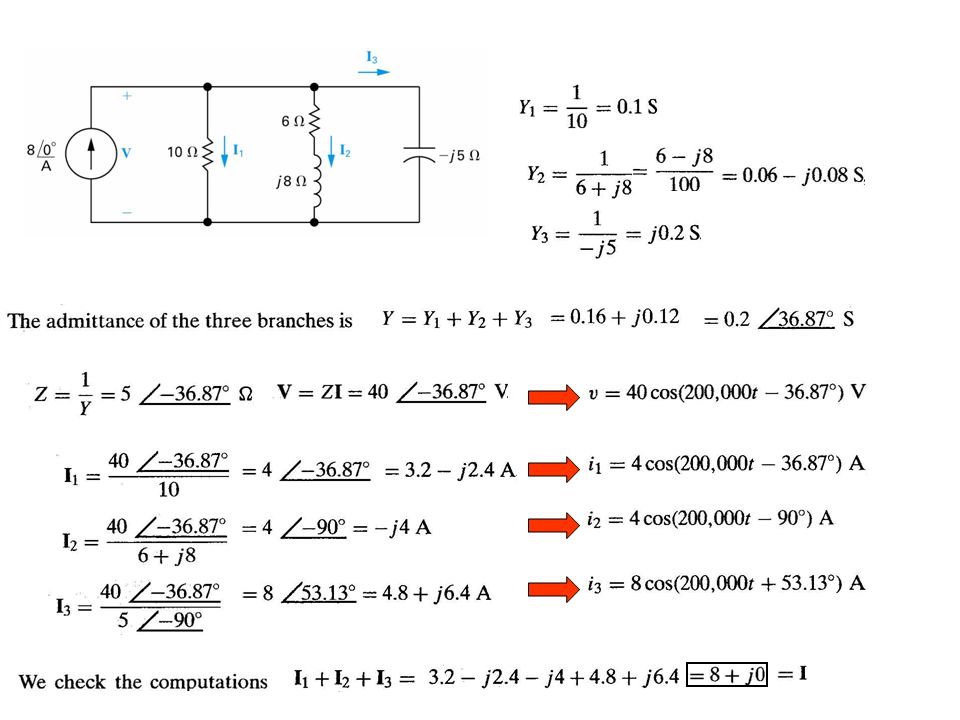
Example 9.7 Combining Impedances in series and in Parallel (a) Construct the frequency-domain (phasor, complex) equivalent circuit ? (b) Find the steady state expressions for v,i 1, i 2, and i 3 ? ? (a)
 Find the steady state expressions for v,i 1, i 2, and i 3 . (a).")
53
Ex 6.4:Determine the voltage v(t) in the circuit Impedance of capacitor is
 in the circuit Impedance of capacitor is")
54
A single-node pair circuit Hence time-domain voltage becomes

55
Ex 6.5 Determine the current i(t) and voltage v(t) Single loop phasor circuit The current By voltage division The time-domain
 and voltage v(t) Single loop phasor circuit The current By voltage division The time-domain")
56
Ex 6.6 Determine the current i(t) The phasor circuit is Combine resistor and inductor
 The phasor circuit is Combine resistor and inductor")
57
Use current division to obtain capacitor current Hence time-domain current is:

58
9.7 Source Transformations and Thevenin-Norton Equivalent Circuits Source Transformations Thevenin-Norton Equivalent Circuits

59
Example 9.9

60
Ex 6.7 Determine i(t) using source transformation Phasor circuit Transformed source Voltage of source: Hence the current In time-domain
 using source transformation Phasor circuit Transformed source Voltage of source: Hence the current In time-domain")
61
Phasor circuit Ex 6.9 Find voltage v(t) by reducing the phasor circuit at terminals a and b to a Thevenin equivalent Remove the load Voltage Divsion
 by reducing the phasor circuit at terminals a and b to a Thevenin equivalent Remove the load Voltage Divsion")
62
parallel

63
The Thevenin impedance can be modeled as 1.19 resistor in series with a capacitor with value or

Similar presentations


 Hung-yi Lee. Textbook Chapter 6.1.>")

 Sinusoidal Steady-State Analysis>")


 produces a current That varies sinusoidally with time.>")

