Download presentation
Presentation is loading. Please wait.

1
UML Diagrams: Sequence Diagrams The Requirements Model, and The Dynamic Analysis Model Instructor: Dr. Hany H. Ammar Dept. of Computer Science and Electrical Engineering, WVU

2
Outline n Review of previous Lecture n The Requirements Model and the Analysis model n Importance of Sequence Diagrams n Rules of sequence diagrams n Use Cases and Sequence Diagrams n The System Sequence Diagrams n The Sound Recorder Example n The E-Commerce Example n Other Examples

3
Review of Previous lecture n Review of development phases and UML Development - Overview n Introduction and importance of Use Case Diagrams n Use Case Diagram Rules n Examples of Use Case diagrams n Requirements Elicitation Process 1. Identify Actors 2. Identify Scenarios 3. Identify Use Cases 4. Refine Use Cases 5. Identify Relationships between actors and Use Cases 6. Identify Initial Analysis Objects 7. Identify Non-functional requirements

4
UML Development - Overview PROGRAM ACTORS ANALYSIS Specify Domain Objects Detailed DESIGN IMPLEMENTATION D A T A D I C T I O N A R Y Time USE CASES ANALYSIS CLASS DIAGRAM(S) IMPLEMENTATION Activity DIAGRAMS System/Object SEQUENCE DIAGRAMS OPERATION CONTRACTS StateChart DIAGRAMs DEPLOYMENT DIAGRAM SUBSYSTEM CLASS/ OR COMPONENT DIAGRAMS Architectural Design Include Design Objects Object Design SCENARIOS REQUIREMENTS ELICITATION DESIGN DIAGRAMS IMPLEMENTATION CHOICES DESIGN SEQUENCE DIAG. Requirements Engineering

5
Where are we in the Requirements Engineering ? n Requirements Engineering focus: elicitation and analysis

6
The Requirements Model and the Analysis Model Static Analysis Dynamic Analysis Functional/ Nonfunctional Requirements Use Case Diagrams/ Sequence Diagrams (the system level) - Class Diagrams - State Diagrams/ Refined Sequence Diagrams (The object level) The Requirements Elicitation Process The Object-Oriented Analysis Process
 - Class Diagrams - State Diagrams/ Refined Sequence Diagrams (The object level) The Requirements Elicitation Process The Object-Oriented Analysis Process")
7
Outline n The Requirements Model and the Analysis model n Introduction to Requirements Engineering n Importance of Sequence Diagrams n Rules of sequence diagrams n Use Cases and Sequence Diagrams n The System Sequence Diagrams n The Sound Recorder Example n The E-Commerce Example n Other Examples

8
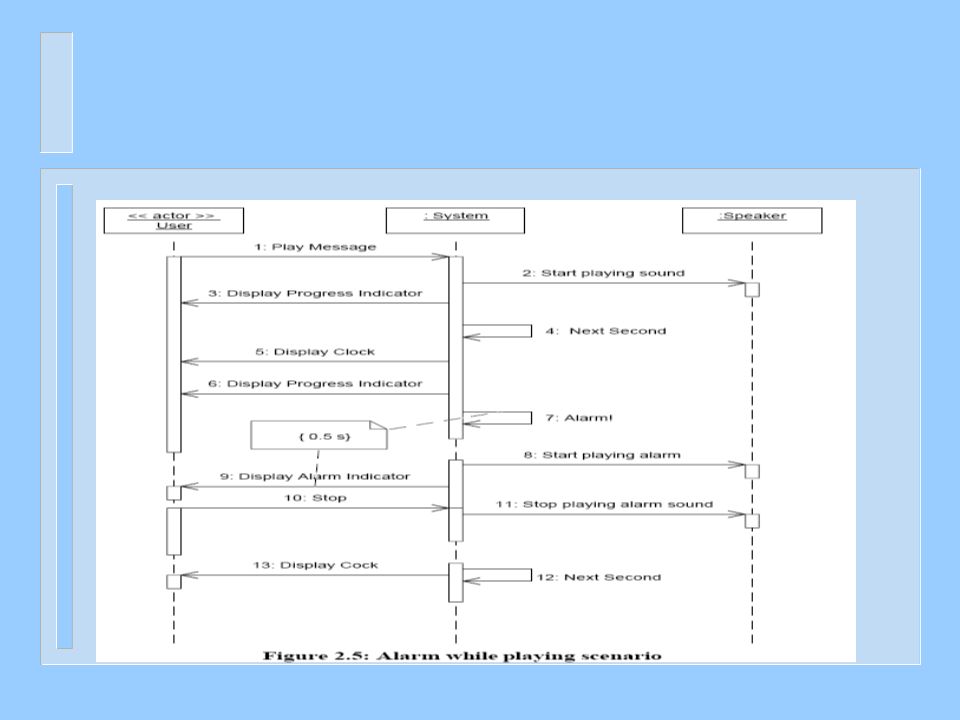
Importance of Sequence Diagrams n Depict object interactions in a given scenario identified for a given Use Case n Specify the messages passed between objects using horizontal arrows including messages to/from external actors n Time increases from Top to bottom

9
Rules of Sequence Diagrams n Sequence Initiation

10
Rules of Sequence Diagrams Identify objects needed to support use cases, determine sequence of internal events following the external initiating event n Diagrams that are not initiated with an external actor represent only a partial sequence n Partial sequence diagrams should clearly identify the actor initiated sequence diagrams from which they are launched

11
Example of Sequence Diagrams Notation

12
Rules of Sequence Diagrams n Messages specified on interactions can be synchronous or asynchronous Synchronous call

13
Rules of Sequence Diagrams Asynchronous call

14
Rules of Sequence Diagrams n Display operation names on call arrows

15
Rules of Sequence Diagrams Compound and Simple Iteration

16
‘included’ sequence diagrams

17
Showing alternate behavior in a sequence diagram

18
Rules of Sequence Diagrams Showing alternate behavior in a sequence diagram

19
Showing Extension Point

20
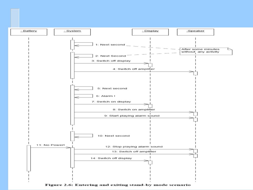
Specifying Timing Requirements

21
Outline n The Requirements Model and the Analysis model n Introduction to Requirements Engineering n Importance of Sequence Diagrams n Rules of sequence diagrams n Use Cases and Sequence Diagrams n The System Sequence Diagrams n The Sound Recorder Example n The E-Commerce Example n Other Examples

22
Recall Requirements Elicitation Process n The process of requirements elicitation consists of the following steps 1. Identify Actors 2. Identify Scenarios 3. Identify Use Cases 4. Refine Use Cases 5. Identify Relationships between actors and Use Cases 6. Identify Initial Analysis Objects 7. Identify Non-functional requirements

23
Requirements Elicitation Process Step 4. Refining Use Cases System Sequence Diagrams n System sequence diagrams establish the dynamic behavior in terms of key scenarios of the system for each use case n The system sequence diagram models a scenario of the system interactions with the environment for a given use case n Input/output events are clearly identified in each sequence diagram, n The State of the system before and after each event are also depicted n Different diagrams model scenarios with the normal flow of events and the abnormal flow of events

24
Sequence Diagrams and Use Cases System Sequence Diagram The sequence diagram of use case UC1 for system S The use case diagram Of system S

25
UML Use Case Diagrams: The Requirements Model Case Study

26
UML Use Case Diagrams: The Requirements Model Digital Sound Recorder Case Study n A sequence diagram displays object interactions arranged in a time sequence capturing a specific scenario of interactions in a use case supported by the system Time

29
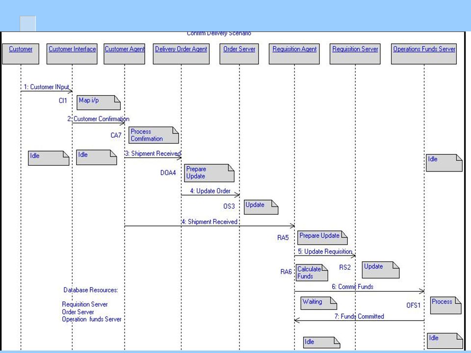
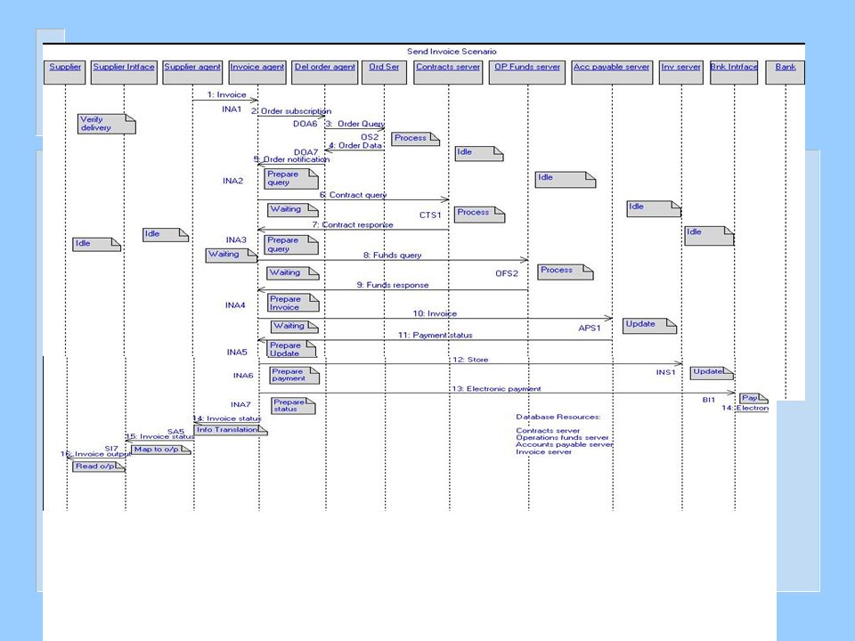
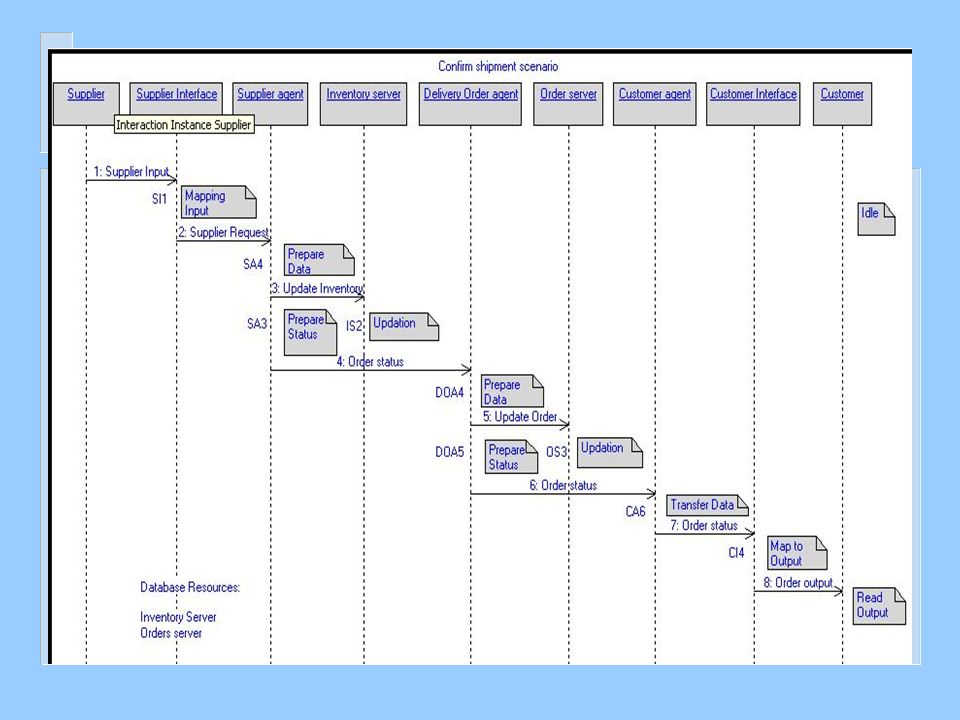
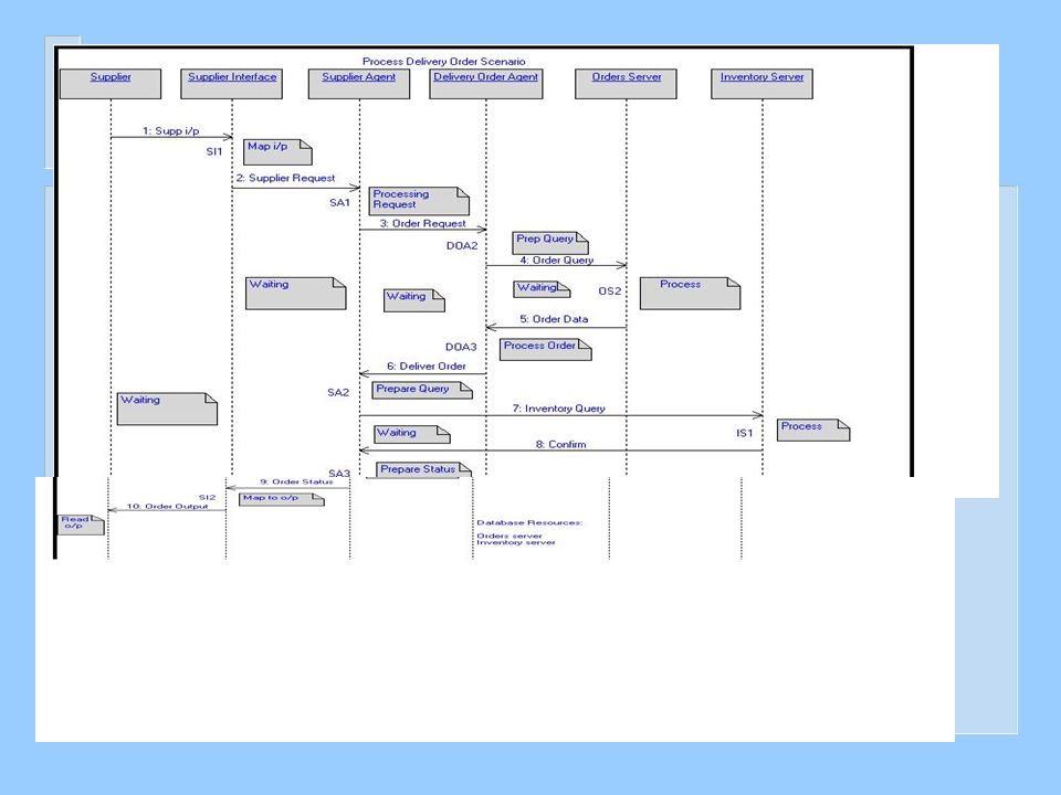
Example: Use Case Diagram of E-Commerce Example

30
Place Requistion

35
A Simple Example of Using UML2 n EXAMPLE: SATELLITE CONTROL SYSTEM

36
Example of Software Architecture Using UML2 n SATELLITE CONTROL SYSTEM Architecture

37
A Simple Example Using UML2 n SATELLITE CONTROL SYSTEM Architectural behavior

Similar presentations


 Presentation By - SANDEEP REDDY CHEEDEPUDI (Student No: 17037032) - VISHNU CHANDRADAS (Student.>")


 diagram Describes object interaction Typically captures behavior of a single use case.>")
>")

 Fawzi Emad Chau-Wen Tseng Department of Computer Science University of Maryland, College Park.>")


