Download presentation
Presentation is loading. Please wait.

2
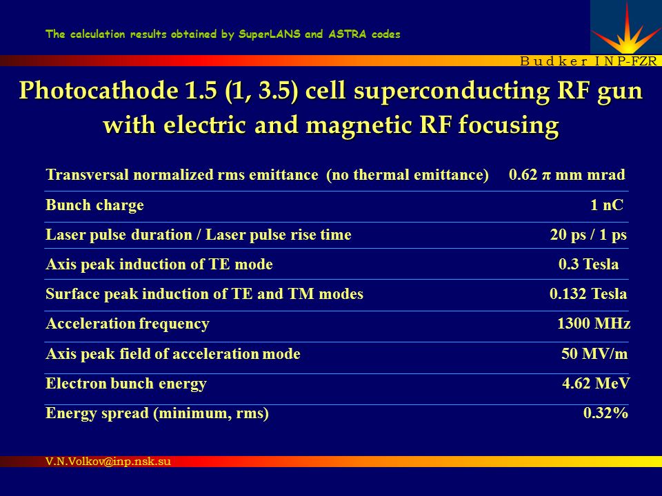
Photocathode 1.5 (1, 3.5) cell superconducting RF gun with electric and magnetic RF focusing Transversal normalized rms emittance (no thermal emittance) 0.62 π mm mrad Bunch charge 1 nC Laser pulse duration / Laser pulse rise time 20 ps / 1 ps Axis peak induction of TE mode 0.3 Tesla Surface peak induction of TE and TM modes 0.132 Tesla Acceleration frequency 1300 MHz Axis peak field of acceleration mode 50 MV/m Electron bunch energy 4.62 MeV Energy spread (minimum, rms) 0.32% B u d k e r I N P-FZR V.N.Volkov@inp.nsk.su The calculation results obtained by SuperLANS and ASTRA codes
 cell superconducting RF gun with electric and magnetic RF focusing Transversal normalized rms emittance (no thermal emittance) 0.62 π mm mrad Bunch charge 1 nC Laser pulse duration / Laser pulse rise time 20 ps / 1 ps Axis peak induction of TE mode 0.3 Tesla Surface peak induction of TE and TM modes Tesla Acceleration frequency 1300 MHz Axis peak field of acceleration mode 50 MV/m Electron bunch energy 4.62 MeV Energy spread (minimum, rms) 0.32% B u d k e r I N P-FZR The calculation results obtained by SuperLANS and ASTRA codes")
3
RF gun geometry. What are the electric and magnetic RF focusing? 1 – Heat sink 2 – Choke cell 3 – Photocathode Cu stalk 4 – Cathode cell 5 – Electric TM field pattern 6 – Magnetic TE field pattern 7 – Cavity full cell 8 – TE mode coupler (90º routed) 9 – TM mode coupler pipe Scaled cathode region Cu T=78K T= 78K Electric RF focusing region Magnetic RF focusing region
 9 – TM mode coupler pipe Scaled cathode region Cu T=78K T= 78K Electric RF focusing region Magnetic RF focusing region.")
4
Other injector parameters Acceleration field frequency1300 MHz Acceleration peak field at the cavity axis50 MV/m Launch phase of bunch centre (optimized)55º55º Laser spot radius at the photocathode (optimized) 1.5 mm Depth of photocathode Cu stem in back cavity wall (optimized to create optimal RF focusing) 2 mm External quality factor of input coupler (Q ext )3.79·10 5 Input power / Average beam current assuming the Q ext 320 kW / 70 mA Dissipated 1300 MHz power at Cu pipe of input coupler assuming the Q ext and T Cu =78K 9.4 W Dissipated 1300 MHz power at cavity Nb wall (assuming unloaded quality factor Q o =10 10, 2K) 12.13 W Dissipated 1300 MHz power at photocathode Cu stem assuming T Cu =78K 5 W Surface peak field at the photocathode32.8 MV/m Frequency of magnetic focusing TE mode3788 MHz Axis peak induction of TE mode (optimized)0.3 Tesla Maximum vector sum of surface induction of 1300 and 3788 MHz (the limit is 0.18 Tesla) 0.132 Tesla Surface peak induction of TE mode0.108 Tesla Ratio of Peak Induction on the surface and on the axis (RPI) 0.358 Unloaded Quality factor of TE mode assuming the Q o for 1300 MHz 0.85·10 8 Dissipated RF power of TE mode at cavity Nb wall 13.43 W Dissipated RF power of TE mode at Cu pipe of input coupler assuming T Cu =78K 3.63 W Transversal normalized emittance of bunch (thermal emittance is not taken into account) 0.62 π mm mrad Full emittance: thermal emittance of Cs 2 Te photocathode (0.64 m) is taken into account 0.89 π mm mrad Axis coordinate of emittance minimum disposition from the cathode 0.85 m
55º55º Laser spot radius at the photocathode (optimized) 1.5 mm Depth of photocathode Cu stem in back cavity wall (optimized to create optimal RF focusing) 2 mm External quality factor of input coupler (Q ext )3.79·10 5 Input power / Average beam current assuming the Q ext 320 kW / 70 mA Dissipated 1300 MHz power at Cu pipe of input coupler assuming the Q ext and T Cu =78K 9.4 W Dissipated 1300 MHz power at cavity Nb wall (assuming unloaded quality factor Q o =10 10, 2K) W Dissipated 1300 MHz power at photocathode Cu stem assuming T Cu =78K 5 W Surface peak field at the photocathode32.8 MV/m Frequency of magnetic focusing TE mode3788 MHz Axis peak induction of TE mode (optimized)0.3 Tesla Maximum vector sum of surface induction of 1300 and 3788 MHz (the limit is 0.18 Tesla) Tesla Surface peak induction of TE mode0.108 Tesla Ratio of Peak Induction on the surface and on the axis (RPI) Unloaded Quality factor of TE mode assuming the Q o for 1300 MHz 0.85·10 8 Dissipated RF power of TE mode at cavity Nb wall W Dissipated RF power of TE mode at Cu pipe of input coupler assuming T Cu =78K 3.63 W Transversal normalized emittance of bunch (thermal emittance is not taken into account) 0.62 π mm mrad Full emittance: thermal emittance of Cs 2 Te photocathode (0.64 m) is taken into account 0.89 π mm mrad Axis coordinate of emittance minimum disposition from the cathode 0.85 m")
5
RF fields in the cavity /SLANS cod The vectors of TE and TM fields are ortogonal F=1300 MHz F=3788 MHz E50 MV/m axis B TE 0.3 T axis B TM 0.128 T surface B TE 0.108 T surface B TM +B TE 0.132 T surface Peak fields

6
High order TE modes selection for low Ratio of Peak Induction (RPI) at the surface and at the axis F, MHz RPI 2572.50.539 3787.80.358 3899.70.819 3947.20.863 F=2572.5 MHzF=3787.8 MHz F=3899.7 MHzF=3947.2 MHz TE 021 Pipe cut off TE frequency 5226 MHz TE 011
 at the surface and at the axis F, MHz RPI F= MHzF= MHz F= MHzF= MHz TE 021 Pipe cut off TE frequency 5226 MHz TE 011")
7
Emittance dependence from TE field phase n – transversal normalized rms emittance av - average emittance A – emittance amplitude φ TE – TE mode phase o - constant phase B TE – TE mode peak induction at the axis, T R – laser spot radius at the photocathode, mm TM – launch phase (here TM =50º at maximum bunch energy) ε av, m 0.8050.712 A ε, m 0.2120.08 B TE, T 0.280.3 R, mm 1.01.5 12 Set examples
 ε av, m A ε, m B TE, T R, mm Set examples")
8
Parameter scanning for emittance minimization / ASTRA cod TE induction (B TE ), laser spot size (R), launch phase ( TM ) ++ 1.0 1.25 1.5 1.75 R,mm 1.0 1.25 1.5 1.75 R, mm 0.32 0.30 0.28 0.26 0.32 0.30 0.28 0.26 B TE,T Average emittance, mEmittance amplitude, m φ TM =46.3º B TE =0.29 T R=1.5 mm ε min =0.7 m Extreme valuesφ TM Average emittance, m 0.6255º Emittance amplitude, m 0!60º Energy, MeV4.6250º Energy spread, KeV1542º Launch phase scanning + 0.7 + Optimum for n =5%: B TE =0.03T DR=0.6 mm TM =10º Sensitivity
, laser spot size (R), launch phase ( TM ) R,mm R, mm B TE,T Average emittance, mEmittance amplitude, m φ TM =46.3º B TE =0.29 T R=1.5 mm ε min =0.7 m Extreme valuesφ TM Average emittance, m º Emittance amplitude, m 0!60º Energy, MeV4.6250º Energy spread, KeV1542º Launch phase scanning Optimum for n =5%: B TE =0.03T DR=0.6 mm TM =10º Sensitivity")
9
Bunch time evolution Phase space, KeV/c X, mm Bunch cross section, mm Bunch rotation is subtracted here Bunch rotates by magnetic TE field 60 cm drift

10
Emittance compensation instances: without any RF focusing, with only electric RF focusing, with only magnetic RF focusing, with sum - electric and magnetic RF focusing Optimized settings & performances Without any RF focusing Electric RF focusing only Magnetic RF focusing only Electric and magnetic RF focusing ε n, mm mrad 3.661.491.280.62 ( ε n 2 + ε th 2 ) 1/2 3.761.721.440.89 R (laser), mm 221.5 φ TM, deg 49.4º46.3º49.4º55º Cathode depth, mm 0202 B TE (axis, peak), T 000.3 B (surf., peak), T 0.128 0.132 mm mrad] - Cs 2 Te photocathode thermal normalized emittance [ K.Floettmann studed ]
![Emittance compensation instances: without any RF focusing, with only electric RF focusing, with only magnetic RF focusing, with sum - electric and magnetic RF focusing Optimized settings & performances Without any RF focusing Electric RF focusing only Magnetic RF focusing only Electric and magnetic RF focusing ε n, mm mrad ( ε n 2 + ε th 2 ) 1/ R (laser), mm φ TM, deg 49.4º46.3º49.4º55º Cathode depth, mm 0202 B TE (axis, peak), T B (surf., peak), T mm mrad] - Cs 2 Te photocathode thermal normalized emittance [ K.Floettmann studed ]](http://images.slideplayer.com/33/7731023/slides/slide_10.jpg "Emittance compensation instances: without any RF focusing, with only electric RF focusing, with only magnetic RF focusing, with sum - electric and magnetic RF focusing Optimized settings & performances Without any RF focusing Electric RF focusing only Magnetic RF focusing only Electric and magnetic RF focusing ε n, mm mrad ( ε n 2 + ε th 2 ) 1/ R (laser), mm φ TM, deg 49.4º46.3º49.4º55º Cathode depth, mm 0202 B TE (axis, peak), T B (surf., peak), T mm mrad] - Cs 2 Te photocathode thermal normalized emittance [ K.Floettmann studed ]")
11
1 cell superconducting RF gun (“DROSSEL”) with electric and magnetic RF focusing Optimized performances Bunch transv. norm.emitt., m 0.51÷0.52 Emitt. minimum disposition, m 0.265 Average Energy, MeV 2.26 Launch phase of 1300 MHz 25.0º Laser spot radius, mm 1.5 B TE (peak,, axis), T 0.300 B TE (peak, surface), T 0.168 RPI 0.56 B TM (surface), mT 0.123 | B TM + B TE |, mT 0.173 Emittance TE compensation TE 021
, T B TE (peak, surface), T RPI 0.56 B TM (surface), mT | B TM + B TE |, mT Emittance TE compensation TE 021.")
12
3.5 cell superconducting RF gun with electric and magnetic RF focusing Bunch transv. norm.emitt., m 0.78÷0.98 Emitt. minimum disposition, m 4.25 Average Energy, MeV 8.82 Launch phase of TM 1300 MHz 74.6º Laser spot radius, mm 1.5 B TE (peak, axis), T 0.324 B TE (peak, surface), T 0.136 RPI 0.42 B TM (surface), mT 0.115 | B TM + B TE |, mT 0.144 TE 021
, T B TE (peak, surface), T RPI 0.42 B TM (surface), mT | B TM + B TE |, mT TE 021.")
13
Conclusions Emittance compensation by the electric and magnetic RF focusing as well as a high accelerating gradient are the key factors in getting a small emittance with a large charge. Either electric or magnetic RF focusing diminish the emittance more than twice. And together – about 6 times. The peak induction of magnetic field on the axis is about 0.3 T. And sum of magnetic fields on cavity surface is less than the limit of 0.18 T. The induction of peak magnetic field on cavity surface proved to be small due to vector summation of orthogonal TE and TM fields. Also because of an unoverlapping of their peak fields on the surface. TE 021 mode has a smallest ratio of magnetic peak induction on the surface to the peak induction on the axis. The dependence of emittance from TE phase has oscillatory view. There are RF gun parameter settins at which the oscillatory amplitude becomes zero. Transversal emittance remains small in wide range of RF gun settings.

14
Acknowledgments The author would like to thank Dietmar Janssen (FZR), Klauss Floettmann (DESY), Victor Petrov (BINP) for helping in the work.
, Klauss Floettmann (DESY), Victor Petrov (BINP) for helping in the work.")
Similar presentations
 ● 2BC (rf-rf-bc-rf-bc-rf) ● table: 2BC (rf-rf-bc-rf-bc-rf) dogleg + 2BC (rf-dog-rf-rf-bc-rf-bc-rf)>")


