Download presentation
Presentation is loading. Please wait.

1
Ultra-Wideband Research and Implementation By Jarrod Cook and Nathan Gove Advisors: Dr. Brian Huggins Dr. In Soo Ahn Dr. Prasad Shastry

2
Presentation Outline Introduction Introduction Overview Overview Project Summary Project Summary Spectrum Overview Spectrum Overview Modulation Modulation Project Issues Project Issues Time Constraints Time Constraints Sampling Rates Sampling Rates ADC / DAC issue ADC / DAC issue Project Schedule Project Schedule Website Updates Website Updates Project Milestones Project Milestones Model Model Block Diagram Block Diagram Frame Synchronization Frame Synchronization Integration with CCS and DSPs Integration with CCS and DSPs Hardware Hardware 2/3 of Hardware Received 2/3 of Hardware Received LO Tested LO Tested Future Work Future Work Questions? Questions?

3
Introduction to UWB Ultra-wideband technology is a wireless transmission technique approved for unlicensed use in 2002 under the FCC Part 15 Ultra-wideband technology is a wireless transmission technique approved for unlicensed use in 2002 under the FCC Part 15 Ideal for portable multimedia devices because of its inherent low power consumption and high bit rates Ideal for portable multimedia devices because of its inherent low power consumption and high bit rates

4
Why Research UWB? UWB is likely to revolutionize the consumer electronic market in the near future. UWB is likely to revolutionize the consumer electronic market in the near future. Wireless USB devices Wireless USB devices Wireless communication for High-Definition devices Wireless communication for High-Definition devices UWB has the power to eliminate the majority of wires to and from multimedia devices UWB has the power to eliminate the majority of wires to and from multimedia devices

5
Overview Brief History Brief History IEEE 802.15.3a IEEE 802.15.3a ECMA 368 and 369 ECMA 368 and 369 Consumer Electronics Demand Consumer Electronics Demand High data-rate wireless transmissions High data-rate wireless transmissions Low power consumption for portable devices Low power consumption for portable devices UWB allows data rates equivalent to UWB allows data rates equivalent to USB 2.0 (480 Mb/s)
")
6
Project Summary The goal of this project is to complete a scaled- down version of a UWB transceiver pair. The goal of this project is to complete a scaled- down version of a UWB transceiver pair. Specifically, we are focusing on the following: Specifically, we are focusing on the following: Understanding the theory Understanding the theory Simulink modeling Simulink modeling DSP implementation DSP implementation RF transceiver hardware RF transceiver hardware Testing Testing

7
UWB Spectrum Overview Power spectral density Power spectral density -41.3 dBm/MHz -41.3 dBm/MHz FCC part 15 limit FCC part 15 limit Frequency Range Frequency Range 3.1 to 10.6 GHz 3.1 to 10.6 GHz Sub-bands Sub-bands

8
Modulation QPSK or 4-QAM QPSK or 4-QAM Gray Coded Mapping Gray Coded Mapping Symbols Symbols Used for data rates from 80 to 200 Mb/s Used for data rates from 80 to 200 Mb/s I & Q I & Q 16-QAM or DCM 16-QAM or DCM Used for data rates from 320 Mb/s to 480 Mb/s Used for data rates from 320 Mb/s to 480 Mb/s

9
OFDM

10
OFDM Benefits Benefits Resistance to multi-path fading Resistance to multi-path fading Spectrum Spectrum Full ECMA standardized UWB spectrum Full ECMA standardized UWB spectrum Scaled-down project spectrum Scaled-down project spectrum

11
Project Issues Due to Time Constraints Due to Time Constraints Power Limitation Power Limitation Must be overlooked for this initial project Must be overlooked for this initial project Output of quadrature modulators exceed limitations Output of quadrature modulators exceed limitations Transmission Bandwidth / Data Rate Transmission Bandwidth / Data Rate ACD and DAC are not sufficient ACD and DAC are not sufficient Audio Development Kit Audio Development Kit UWB Coding Specifications 20% Met UWB Coding Specifications 20% Met Pseudo-random code / spreading / time interleaving Pseudo-random code / spreading / time interleaving Forward Error Correcting Forward Error Correcting Data frame will not include full preambles / headers Data frame will not include full preambles / headers

12
Project Issues Sampling Times Sampling Times Simulink requires information at equal times Simulink requires information at equal times Must be very careful when changing sampling rates Must be very careful when changing sampling rates ADC / DAC Issues ADC / DAC Issues DAC DAC Need to Transmit In Phase and Quadrature Phase Components Need to Transmit In Phase and Quadrature Phase Components DACs can only output real numbers DACs can only output real numbers Two DACs are required Two DACs are required Board only has one DAC Board only has one DAC Daughter Boards Required Daughter Boards Required Both Both With faster converters, wider bandwidths possible With faster converters, wider bandwidths possible

13
Overall Tx / Rx Block Diagram

14
Simulink Model Model Model Frame Synchronization Frame Synchronization Preamble Complete Preamble Complete

15
Updated Project Schedule

16
Updates on Project Website UWB Website Updates UWB Website Updates UWB Website Updates UWB Website Updates

17
Progress DSP Platforms received C6416 DSK

18
Integration of Simulink with CCS To use the DSP boards, all that has to be added to the model is the “C6416DSK” block. Simulink has a blockset for this model Allows use of ADC and DAC LEDs DIP Switches Software Reset Running the model automatically launches CCS which converts the model to C-code and uploads it.

19
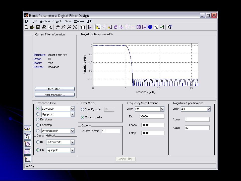
Simple DSP Test with CCS DSP Platform Hardware Tested with Simulink and Code Composer Studio (CCS) Used a FIR Filter for a quick test
 Used a FIR Filter for a quick test")
20
Simple Test Cont. Once we figured out how to successfully upload models, we did a quick FIR filter model to test the model. Sampling rate: 32 kHz Passband: 0 to 5 kHz Stopband: 6 kHz Results Did a quick frequency sweep of the filter through the DSP to visually confirm the DSP was working

22
RF Hardware The RF local oscillator and direct quadrature modulator have arrived.

23
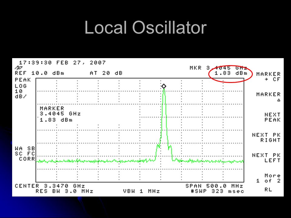
Local Oscillator Test The oscillator was tested on the spectrum analyzer to verify that it met the specifications stated in the data sheet. Data sheet specs: Tunable from 3.35 to 3.55 GHz Typical power output: 4.7 dBm (1.5 minimum) Current draw: 41 mA Harmonic levels: -7 and -16 dBc
 Current draw: 41 mA Harmonic levels: -7 and -16 dBc.")
24
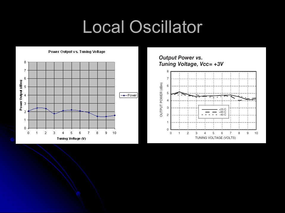
Local Oscillator Tests performed: Output frequency vs. tuning voltage Output power vs. tuning voltage Harmonic power levels The frequency vs. tuning voltage matched up with the data sheet nicely The output power was much lower than the specs (on the order of 0.5 to 1.2 dBm) Determined the loss of the coax, DC block, and connectors to be around 1 dB. Therefore, results are more normal Harmonic Power levels matched data sheet specs
 Determined the loss of the coax, DC block, and connectors to be around 1 dB. Therefore, results are more normal Harmonic Power levels matched data sheet specs.")
25
Local Oscillator

28
Harmonic Power Levels Frequency (GHz) Power (dBm)Power away from carrier (dBc) 3.411.6 6.88-4.6-6.2 10.29-15.5-17.1 13.67-28.4-30.0
 Power (dBm)Power away from carrier (dBc)")
29
Local Oscillator

31
Future hardware testing Quadrature Modulator Quadrature De-Modulator Interconnecting all the hardware for testing Transmission lines as channel before wireless Signal leaves DSP on a 3.5mm audio jack, and must be received by the modulator with an SMA connector. Impedance mismatches?

32
Hardware Connections

33
Future Work Previous To Do List Current To Do List Baseband processor Increase complexity Research UWB channels (no longer implementing) Determine maximum feasible sampling rate Purchase DSP board Implement synchronous coherent detection for receiver RF Transmitter Find a suitable quadrature modulator Determine and purchase hardware Model and Design (no longer implementing) Fabricate hardware (no longer implementing) Antenna research (no longer implementing) RF Receiver LNA Design and modeling (N. L. I.) Determine and purchase hardware Fabricate hardware (N. L. I.) Testing Transmitter Implement Daughterboard DACs and ADCs Receiver Complete Frame Synchronization Pulse on Frame Start Frame Alignment Implement Carrier Synchronization Using the Pilot Signals correct for the phase error. Testing System Integration Full system testing Bandwidth measurements Bit Error Rates Other common communication systems measurements.
 Determine and purchase hardware Fabricate hardware (N. L. I.) Testing Transmitter Implement Daughterboard DACs and ADCs Receiver Complete Frame Synchronization Pulse on Frame Start Frame Alignment Implement Carrier Synchronization Using the Pilot Signals correct for the phase error. Testing System Integration Full system testing Bandwidth measurements Bit Error Rates Other common communication systems measurements..")
34
Questions ?? U W B Standards

Similar presentations


 One of the main problems in OFDM system is large PAPR /PAR(increased complexity of the ADC and DAC, and reduced efficiency.>")


 at 2.4 GHz Perform baseband processing and digital up and down conversion on Nallatech.>")


