Download presentation
Presentation is loading. Please wait.

1
A Discussion of CPU vs. GPU 1

2
CUDA Real “Hardware” Intel Core 2 Extreme QX9650 NVIDIA GeForce GTX 280 NVIDIA GeForce GTX 480 Transistors820 million1.4 billion3 billion Processor frequency 3 GHz1296 MHz1401 MHz Cores4240480 Cache/Shared Memory 6 MB x 216 KB x 3016KB Threads executed per cycle 4240480 Active hardware threads 43072061440 Peak FLOPS96 GFLOPS933 GFLOPS1344 GFLOPS Memory controllersoff-die8 x 64 bit Memory bandwidth12.8 GBps141.7 GBps177.4 GBps

3
CPU vs. GPU Theoretic Peak Performance *Graph from the NVIDIA CUDA Programmers Guide, http://nvidia.com/cuda 3

4
CUDA Memory Model

5
CUDA Programming Model

6
Memory Model Comparison OpenCL CUDA

7
CUDA vs OpenCL

8
A Control-structure Splitting Optimization for GPGPU Jakob Siegel, Xiaoming Li Electrical and Computer Engineering Department University of Delaware 8

9
CUDA Hardware and Programming Model Grid of Thread Blocks Blocks mapped to Streaming Multiprocessors (SM) SIMT Manages threads in warps of 32 Maps threads to Streaming Processors (SP) Threads start together but are free to branch 9 *Graph from the NVIDIA CUDA Programmers Guide, http://nvidia.com/cuda
 SIMT Manages threads in warps of 32 Maps threads to Streaming Processors (SP) Threads start together but are free to branch 9 *Graph from the NVIDIA CUDA Programmers Guide,")
10
Thread Batching: Grids and Blocks A kernel is executed as a grid of thread blocks – All threads share data memory space A thread block is a batch of threads that can cooperate with each other by : – Synchronizing their execution For hazard-free shared memory accesses – Efficiently sharing data through a low latency shared memory Two threads from two different blocks cannot cooperate Host Kernel 1 Kernel 2 Device Grid 1 Block (0, 0) Block (1, 0) Block (2, 0) Block (0, 1) Block (1, 1) Block (2, 1) Grid 2 Block (1, 1) Thread (0, 1) Thread (1, 1) Thread (2, 1) Thread (3, 1) Thread (4, 1) Thread (0, 2) Thread (1, 2) Thread (2, 2) Thread (3, 2) Thread (4, 2) Thread (0, 0) Thread (1, 0) Thread (2, 0) Thread (3, 0) Thread (4, 0) *Graph from the NVIDIA CUDA Programmers Guide, http://nvidia.com/cuda
 Block (1, 0) Block (2, 0) Block (0, 1) Block (1, 1) Block (2, 1) Grid 2 Block (1, 1) Thread (0, 1) Thread (1, 1) Thread (2, 1) Thread (3, 1) Thread (4, 1) Thread (0, 2) Thread (1, 2) Thread (2, 2) Thread (3, 2) Thread (4, 2) Thread (0, 0) Thread (1, 0) Thread (2, 0) Thread (3, 0) Thread (4, 0) *Graph from the NVIDIA CUDA Programmers Guide,")
11
What to Optimize? Occupancy? – Most say that the maximal occupancy is the goal. What is occupancy? Number of threads that actively run in a single cycle. In SIMT, things change. Examine a simple code segment – If (…) … – Else … 11
 … – Else … 11.")
12
SIMT and Branches (like SIMD) If all threads of a warp execute the same branch there is no negative effect. SP time Instruction unit 12 } if { SP

13
SIMT and Branches But if only one thread executes the other branch every thread has to step though all the instructions of both branches. time Instruction unit 13 } else { if { } SP

14
Occupancy Ratio of active warps per multiprocessor to the possible maximum. Effected by : – shared memory usage (16KB/MP*) – registers usage (8192reg/MP*) – block size (512 t/b*) * For a NVIDIA G80 GPU compute model v1.1 14
 – registers usage (8192reg/MP*) – block size (512 t/b*) * For a NVIDIA G80 GPU compute model v")
15
Occupancy and Branches What if the register pressure of the two equally computational intense branches differ? Kernel: 5 registers If-branch: 5 registers else-branch: 7 registers This adds up to a maximum simultaneous usage of 12 registers Limits Occupancy to 67% for a block size of 256 t/b 15

16
Branch-Splitting: Example branchedkernel() { if condition load data for if branch perform calculations else load data for else branch perform calculations end if } 16 if-kernel() { if condition load all input data perform calculations end if } else-kernel() { if !condition load all input data perform calculations end if }
 { if condition load data for if branch perform calculations else load data for else branch perform calculations end if } 16 if-kernel() { if condition load all input data perform calculations end if } else-kernel() { if !condition load all input data perform calculations end if }")
17
Branch-Splitting Idea: Splitting the kernel into two kernels – Each new kernel contains a branch of the original kernel – Adds overhead for: additional kernel invocation additional memory operations – Still all threads have to execute both branches But: One Kernel runs with 100% occupancy 17

18
Synthetic Benchmark: Branch-Splitting branchedkernel() { load decision mask load data used by all branches if decision mask[tid] == 0 load data for if branch perform calculations else // mask == 1 load data for else branch perform calculations end if } 18 if-kernel() { load decision mask if decision mask[tid] == 0 load all input data perform calculations end if } else-kernel() { load decision mask if decision mask[tid] == 1 load all input data perform calculations end if }
![Synthetic Benchmark: Branch-Splitting branchedkernel() { load decision mask load data used by all branches if decision mask[tid] == 0 load data for if branch perform calculations else // mask == 1 load data for else branch perform calculations end if } 18 if-kernel() { load decision mask if decision mask[tid] == 0 load all input data perform calculations end if } else-kernel() { load decision mask if decision mask[tid] == 1 load all input data perform calculations end if }](http://images.slideplayer.com/25/7684088/slides/slide_18.jpg "Synthetic Benchmark: Branch-Splitting branchedkernel() { load decision mask load data used by all branches if decision mask[tid] == 0 load data for if branch perform calculations else // mask == 1 load data for else branch perform calculations end if } 18 if-kernel() { load decision mask if decision mask[tid] == 0 load all input data perform calculations end if } else-kernel() { load decision mask if decision mask[tid] == 1 load all input data perform calculations end if }")
19
Synthetic Benchmark: Linear Growth Decision Mask Decision Mask: Binary mask that defines for each data element which branch to take. 19

20
Synthetic Benchmark: Linear Growing Mask Branched version runs with 67% occupancy Split version: If-kernel 100% Else-kernel 67% else branch executions 20

21
Synthetic Benchmark: Random Filled Decision Mask Decision Mask: Binary mask that defines for each data element which branch to take. 21

22
Synthetic Benchmark: Random Mask Branch execution according to a randomly filled decision mask Worst case single kernel version = Best case for the split version – Every thread steps through the Instructions of both branches else branch executions 22 15%

23
Synthetic Benchmark: Random Mask Branched version: every thread executes both branches and the kernel runs at 67% occupancy Split version: every thread executes both kernels but one kernel runs at 100% occupancy the other one at 67% else branch executions 23

24
Benchmark: Lattice Boltzmann Method (LBM) The LBM models Boltzmann particle dynamics on a 2D or 3D lattice. A microscopically inspired method designed to solve macroscopic fluid dynamics problems. 24

25
LBM Kernels (I) loop_boundary_kernel(){ load geometry load input data if geometry[tid] == solid boundary for(each particle on the boundary) work on the boundary rows work on the boundary columns store result } 25
![LBM Kernels (I) loop_boundary_kernel(){ load geometry load input data if geometry[tid] == solid boundary for(each particle on the boundary) work on the boundary rows work on the boundary columns store result } 25](http://images.slideplayer.com/25/7684088/slides/slide_25.jpg "LBM Kernels (I) loop_boundary_kernel(){ load geometry load input data if geometry[tid] == solid boundary for(each particle on the boundary) work on the boundary rows work on the boundary columns store result } 25")
26
LBM Kernels (II) branch_velocities_densities_kernel(){ load geometry load input data if particles load temporal data for(each particle) if geometry[tid] == solid boundary load temporal data work on boundary store result else load temporal data work on fluid store result } 26
![LBM Kernels (II) branch_velocities_densities_kernel(){ load geometry load input data if particles load temporal data for(each particle) if geometry[tid] == solid boundary load temporal data work on boundary store result else load temporal data work on fluid store result } 26](http://images.slideplayer.com/25/7684088/slides/slide_26.jpg "LBM Kernels (II) branch_velocities_densities_kernel(){ load geometry load input data if particles load temporal data for(each particle) if geometry[tid] == solid boundary load temporal data work on boundary store result else load temporal data work on fluid store result } 26")
27
Splited LBM Kernels if_velocities_densities_kernel( ){ load geometry load input data if particles load temporal data for(each particle) if geometry[tid] == boundary load temporal data work on boundary store result } else_velocities_densities_kern el(){ load geometry load input data if particles load temporal data for(each particle) if geometry[tid] == fluid load temporal data work on fluid store result } 27
![Splited LBM Kernels if_velocities_densities_kernel( ){ load geometry load input data if particles load temporal data for(each particle) if geometry[tid] == boundary load temporal data work on boundary store result } else_velocities_densities_kern el(){ load geometry load input data if particles load temporal data for(each particle) if geometry[tid] == fluid load temporal data work on fluid store result } 27](http://images.slideplayer.com/25/7684088/slides/slide_27.jpg "Splited LBM Kernels if_velocities_densities_kernel( ){ load geometry load input data if particles load temporal data for(each particle) if geometry[tid] == boundary load temporal data work on boundary store result } else_velocities_densities_kern el(){ load geometry load input data if particles load temporal data for(each particle) if geometry[tid] == fluid load temporal data work on fluid store result } 27")
28
LBM Results (128*128) 28
 28")
29
LBM Results (256*256) 29
 29")
30
Conclusion Branches are generally a performance bottleneck in any SIMT architecture Branch Splitting might seem and probably is counter productive on most architectures other than a GPU Experiments show that in many cases the gain in occupancy can increase the performance For a LBM implementation we reduced the execution time by more than 60% by applying Branch Splitting 30

31
Software-based predication for AMD GPUs Ryan Taylor Xiaoming Li University of Delaware

32
Introduction Current AMD GPU: – SIMD (Compute) Engines: Thread processors per SIMD engine – RV770 and RV870 => 16 TPs/SIMD engine – 5-wide VLIW processor (compute cores) – Threads run in Wavefronts Multiple threads per Wavefront depending on architecture – RV770 and RV870 => 64 Threads/Wavefront Threads organized into quads per thread processor Two Wavefront slots/SIMD engine (odd and even)
 Engines: Thread processors per SIMD engine – RV770 and RV870 => 16 TPs/SIMD engine – 5-wide VLIW processor (compute cores) – Threads run in Wavefronts Multiple threads per Wavefront depending on architecture – RV770 and RV870 => 64 Threads/Wavefront Threads organized into quads per thread processor Two Wavefront slots/SIMD engine (odd and even)")
33
AMD GPU Arch. Overview Thread OrganizationHardware Overview

34
Motivation Wavefront Divergence – If threads in a Wavefront diverge then the execution time for each path is serialized Can cause performance degradation Increase ALU Packing – AMD GPU ISA doesn’t allow for instruction packing across control flow operations Reduce Control Flow – Reduce the number of control flow clauses to reduce clause switching

35
Motivation if (cf == 0) { t0 = a + b; t1 = t0 + a; t2 = t1 + t0; e= t2 + t1; } else { t0 = a - b; t1 = t0 - a; t2 = t1 – t0; e= t2 – t1; } 01 ALU_PUSH_BEFORE: ADDR(32) CNT(2) 3 x: SETE_INT R1.x, R1.x, 0.0f 4 x: PREDNE_INT ____, R1.x, 0.0f UPDATE_PRED 02 ALU_ELSE_AFTER: ADDR(34) CNT(66) 5 y: ADD T0.y, R2.x, R0.x 6 x: ADD T0.x, R2.x, PV5.y..... 03 ALU_POP_AFTER: ADDR(100) CNT(66) 71 y: ADD T0.y, R2.x, -R0.x 72 x: ADD T0.x, -R2.x, PV71.y... This example uses hardware predication to decide whether or not to execute a particular path, notice there is no packing across the two code paths.
 CNT(66) 71 y: ADD T0.y, R2.x, -R0.x 72 x: ADD T0.x, -R2.x, PV71.y... This example uses hardware predication to decide whether or not to execute a particular path, notice there is no packing across the two code paths..")
36
Transformation if (cond) ALU_OPs1; output = ALU_OPs1; else ALU_OPs2; output = ALU_OPs2; if (cond) pred1 = 1; else pred2 = 1; ALU_OPS1; ALU_OPS2; output = ALU_OPS1 *pred1+ALU_OPS2*pred2; This example shows the basic idea of the software-based predication technique. Before TransformationAfter Transformation

37
Approach – Synthetic Benchmark if (cf == 0) { t0 = a + b; t1 = t0 + a; t0 = t1 + t0; e= t0 + t1; } else { t0 = a - b; t1 = t0 - a; t0 = t1 – t0; e= t0 – t1; } t0 = a + b; t1 = t0 + a; t0 = t1 + t0; end = t0+ t1; t0 = a - b; t1 = t0 - a; t0 = t1 – t0; if (cf == 0) pred1 = 1.0f; else pred2 = 1.0f; e = (t0-t1)*pred2 + end*pred1; Before TransformationAfter Transformation
 { t0 = a + b; t1 = t0 + a; t0 = t1 + t0; e= t0 + t1; } else { t0 = a - b; t1 = t0 - a; t0 = t1 – t0; e= t0 – t1; } t0 = a + b; t1 = t0 + a; t0 = t1 + t0; end = t0+ t1; t0 = a - b; t1 = t0 - a; t0 = t1 – t0; if (cf == 0) pred1 = 1.0f; else pred2 = 1.0f; e = (t0-t1)*pred2 + end*pred1; Before TransformationAfter Transformation")
38
Approach – Synthetic Benchmark 01 ALU_PUSH_BEFORE: ADDR(32) CNT(2) 3 x: SETE_INT R1.x, R1.x, 0.0f 4 x: PREDNE_INT ____, R1.x, 0.0f UPDATE_PRED 02 ALU_ELSE_AFTER: ADDR(34) CNT(66) 5 y: ADD T0.y, R2.x, R0.x 6 x: ADD T0.x, R2.x, PV5.y 7 w: ADD T0.w, T0.y, PV6.x 8 z: ADD T0.z, T0.x, PV7.w 03 ALU_POP_AFTER: ADDR(100) CNT(66) 9 y: ADD T0.y, R2.x, -R0.x 10 x: ADD T0.x, -R2.x, PV71.y 11 w: ADD T0.w, -T0.y, PV72.x 12 z: ADD T0.z, -T0.x, PV73.w 13 y: ADD T0.y, -T0.w, PV74.z 01 ALU: ADDR(32) CNT(121) 3 y: ADD T0.y, R2.x, -R1.x z: SETE_INT ____, R0.x, 0.0f VEC_201 w: ADD T0.w, R2.x, R1.x t: MOV R3.y, 0.0f 4 x: ADD T0.x, -R2.x, PV3.y y: CNDE_INT R1.y, PV3.z, (0x3F800000, 1.0f).x, 0.0f z: ADD T0.z, R2.x, PV3.w w: CNDE_INT R1.w, PV3.z, 0.0f, (0x3F800000, 1.0f).x 5 y: ADD T0.y, T0.w, PV4.z w: ADD T0.w, -T0.y, PV4.x 6 x: ADD T0.x, T0.z, PV5.y z: ADD T0.z, -T0.x, PV5.w 7 y: ADD T0.y, -T0.w, PV6.z w: ADD T0.w, T0.y, PV6.x Two 20% Packed Instructions One 40% Packed Instruction Reduction in Clauses from 3 to 1
 CNT(2) 3 x: SETE_INT R1.x, R1.x, 0.0f 4 x: PREDNE_INT ____, R1.x, 0.0f UPDATE_PRED 02 ALU_ELSE_AFTER: ADDR(34) CNT(66) 5 y: ADD T0.y, R2.x, R0.x 6 x: ADD T0.x, R2.x, PV5.y 7 w: ADD T0.w, T0.y, PV6.x 8 z: ADD T0.z, T0.x, PV7.w 03 ALU_POP_AFTER: ADDR(100) CNT(66) 9 y: ADD T0.y, R2.x, -R0.x 10 x: ADD T0.x, -R2.x, PV71.y 11 w: ADD T0.w, -T0.y, PV72.x 12 z: ADD T0.z, -T0.x, PV73.w 13 y: ADD T0.y, -T0.w, PV74.z 01 ALU: ADDR(32) CNT(121) 3 y: ADD T0.y, R2.x, -R1.x z: SETE_INT ____, R0.x, 0.0f VEC_201 w: ADD T0.w, R2.x, R1.x t: MOV R3.y, 0.0f 4 x: ADD T0.x, -R2.x, PV3.y y: CNDE_INT R1.y, PV3.z, (0x3F800000, 1.0f).x, 0.0f z: ADD T0.z, R2.x, PV3.w w: CNDE_INT R1.w, PV3.z, 0.0f, (0x3F800000, 1.0f).x 5 y: ADD T0.y, T0.w, PV4.z w: ADD T0.w, -T0.y, PV4.x 6 x: ADD T0.x, T0.z, PV5.y z: ADD T0.z, -T0.x, PV5.w 7 y: ADD T0.y, -T0.w, PV6.z w: ADD T0.w, T0.y, PV6.x Two 20% Packed Instructions One 40% Packed Instruction Reduction in Clauses from 3 to 1")
39
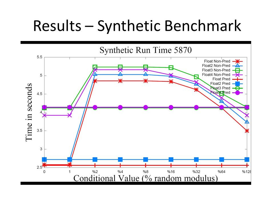
Results – Synthetic Benchmarks Non-Predicated Kernels Instruction Type – Number of Instructions Packing Percent ALUTEXCF 20% (Float)13536 40% (Float2)13538 60% (Float3)13538 80% (Float4)13439 Predicated Kernels Instruction Type – Number of Instructions Packing Percent ALUTEXCF 20% (Float)6834 40% (Float2)6835 60% (Float3)8336 80% (Float4)10937 A reduction in ALU instructions improves performance in ALU bound kernels. Control flow reduction improves performance by reducing clause switching latency.

40
Results – Synthetic Benchmark

42
Pre-Transformation Packing Percentage Divergence20%40%60%80% No Divg.0/0 -22.5/-6.5 1 out of 2 Threads93.5/89.692/8555.7/26.957.7/20.3 1 out of 4 Threads93.5/89.692/8555.7/26.957.7/20.3 1 out of 8 Threads93.5/89.692/8555.7/26.957.7/20.3 1 out of 16 Threads92.6/88.990.9/83.355/26.521.7/15 1 out of 64 Threads61.9/6159.5/5831/9.52.4/3.7 1 out of 128 Threads39.4/36.639.1/37.313.8/.3-11/-6.5 Percent improvement in run time for varying packing ratios for 4870/5870

43
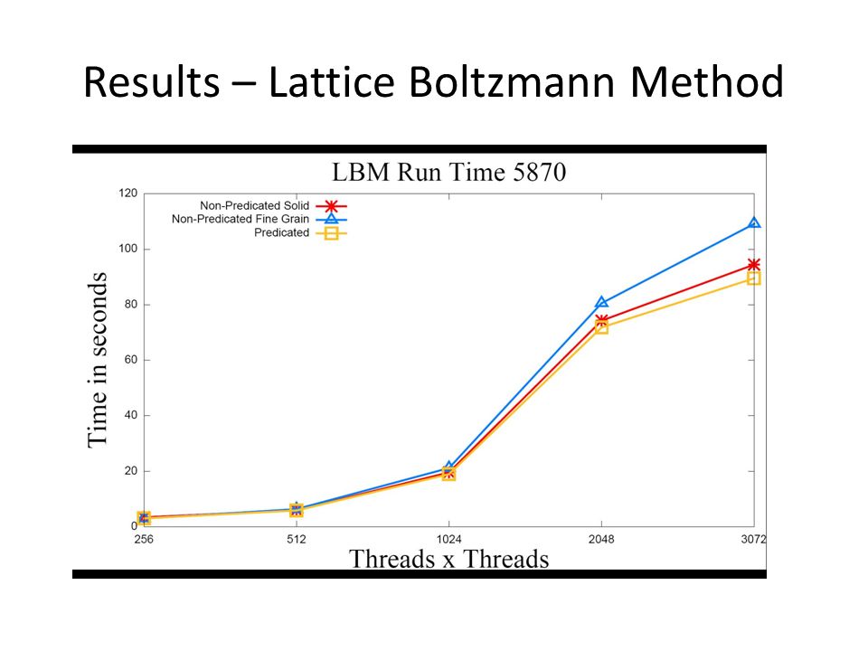
Results – Lattice Boltzmann Method

45
Domain Size X Domain Size Divergence /GPU 256512102420483072 Course Grain/4870 3.23.3 3.6 Fine Grain/4870 7.97.87.78.116.4 Course Grain/5870 3.33.43.3 5.5 Fine Grain/5870 3.38.511.612.121.8 Percent improvement when applying transformation to one path conditionals.

46
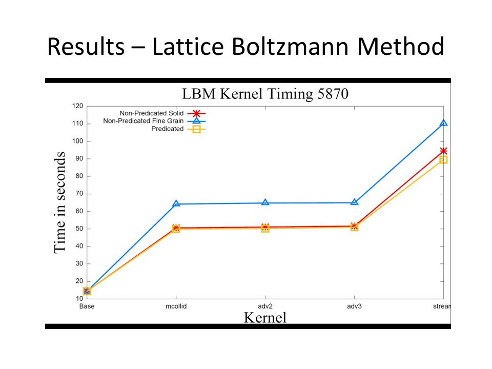
Results – Lattice Boltzmann Method

48
Results – Other (Preliminary) N-queen Solver OpenCL (applied to one kernel) – ALU Packing => 35.2% to 52% – Runtime => 74.3s to 47.2s – Control Flow Clauses => 22 to 9 Stream SDK OpenCL Samples – DwtHaar1D ALU Packing => 42.6% to 52.44% – Eigenvalue Avg Global Writes => 6 to 2 – Bitonic Sort Avg Global Writes => 4 to 2
 N-queen Solver OpenCL (applied to one kernel) – ALU Packing => 35.2% to 52% – Runtime => 74.3s to 47.2s – Control Flow Clauses => 22 to 9 Stream SDK OpenCL Samples – DwtHaar1D ALU Packing => 42.6% to 52.44% – Eigenvalue Avg Global Writes => 6 to 2 – Bitonic Sort Avg Global Writes => 4 to 2")
49
Conclusion Software based predication for AMD GPU – Increases ALU packing – Decreases Control Flow Clause switching – Low overhead Few extra registers needed if any Few additional ALU operations needed – Cheap on GPU – Possibility to pack them in with other ALU operations – Possible reduction in memory operations Combine writes/reads across paths AMD recently introduced this technique in their OpenCL Programming Guide with Stream SDK 2.1

50
A Micro-benchmark Suite for AMD GPUs Ryan Taylor Xiaoming Li

51
Motivation To understand behavior of major kernel characteristics – ALU:Fetch Ratio – Read Latency – Write Latency – Register Usage – Domain Size – Cache Effect Use micro-benchmarks as guidelines for general optimizations Little to no useful micro-benchmarks exist for AMD GPUs Look at multiple generations of AMD GPU (RV670, RV770, RV870)
")
52
Hardware Background Current AMD GPU: – Scalable SIMD (Compute) Engines: Thread processors per SIMD engine – RV770 and RV870 => 16 TPs/SIMD engine – 5-wide VLIW processors (compute cores) – Threads run in Wavefronts Multiple threads per Wavefront depending on architecture – RV770 and RV870 => 64 Threads/Wavefront Threads organized into quads per thread processor Two Wavefront slots/SIMD engine (odd and even)
 Engines: Thread processors per SIMD engine – RV770 and RV870 => 16 TPs/SIMD engine – 5-wide VLIW processors (compute cores) – Threads run in Wavefronts Multiple threads per Wavefront depending on architecture – RV770 and RV870 => 64 Threads/Wavefront Threads organized into quads per thread processor Two Wavefront slots/SIMD engine (odd and even)")
53
AMD GPU Arch. Overview Thread OrganizationHardware Overview

54
Software Overview 00 TEX: ADDR(128) CNT(8) VALID_PIX 0 SAMPLE R1, R0.xyxx, t0, s0 UNNORM(XYZW) 1 SAMPLE R2, R0.xyxx, t1, s0 UNNORM(XYZW) 2 SAMPLE R3, R0.xyxx, t2, s0 UNNORM(XYZW) 01 ALU: ADDR(32) CNT(88) 8 x: ADD ____, R1.w, R2.w y: ADD ____, R1.z, R2.z z: ADD ____, R1.y, R2.y w: ADD ____, R1.x, R2.x 9 x: ADD ____, R3.w, PV1.x y: ADD ____, R3.z, PV1.y z: ADD ____, R3.y, PV1.z w: ADD ____, R3.x, PV1.w 14 x: ADD T1.x, T0.w, PV2.x y: ADD T1.y, T0.z, PV2.y z: ADD T1.z, T0.y, PV2.z w: ADD T1.w, T0.x, PV2.w 02 EXP_DONE: PIX0, R0 END_OF_PROGRAM Fetch Clause ALU Clause
 CNT(8) VALID_PIX 0 SAMPLE R1, R0.xyxx, t0, s0 UNNORM(XYZW) 1 SAMPLE R2, R0.xyxx, t1, s0 UNNORM(XYZW) 2 SAMPLE R3, R0.xyxx, t2, s0 UNNORM(XYZW) 01 ALU: ADDR(32) CNT(88) 8 x: ADD ____, R1.w, R2.w y: ADD ____, R1.z, R2.z z: ADD ____, R1.y, R2.y w: ADD ____, R1.x, R2.x 9 x: ADD ____, R3.w, PV1.x y: ADD ____, R3.z, PV1.y z: ADD ____, R3.y, PV1.z w: ADD ____, R3.x, PV1.w 14 x: ADD T1.x, T0.w, PV2.x y: ADD T1.y, T0.z, PV2.y z: ADD T1.z, T0.y, PV2.z w: ADD T1.w, T0.x, PV2.w 02 EXP_DONE: PIX0, R0 END_OF_PROGRAM Fetch Clause ALU Clause")
55
Code Generation Use CAL/IL (Compute Abstraction Layer/Intermediate Language) – CAL: API interface to GPU – IL: Intermediate Language Virtual registers – Low level programmable GPGPU solution for AMD GPUs – Greater control of CAL compiler produced ISA – Greater control of register usage Each benchmark uses the same pattern of operations (register usage differs slightly)
 – CAL: API interface to GPU – IL: Intermediate Language Virtual registers – Low level programmable GPGPU solution for AMD GPUs – Greater control of CAL compiler produced ISA – Greater control of register usage Each benchmark uses the same pattern of operations (register usage differs slightly)")
56
Code Generation - Generic Reg0 = Input0 + Input1 While (INPUTS) Reg[] = Reg[-1] + Input[] While (ALU_OPS) Reg[] = Reg[-1] + Reg[-2] Output =Reg[]; R1 = Input1 + Input2; R2 = R1 + Input3; R3 = R2 + Input4; R4 = R3 + R2; R5 = R4 + R5; ………….. R15 = R14 + R13; Output1 = R15 + R14;
![Code Generation - Generic Reg0 = Input0 + Input1 While (INPUTS) Reg[] = Reg[-1] + Input[] While (ALU_OPS) Reg[] = Reg[-1] + Reg[-2] Output =Reg[]; R1 = Input1 + Input2; R2 = R1 + Input3; R3 = R2 + Input4; R4 = R3 + R2; R5 = R4 + R5; …………..](http://images.slideplayer.com/25/7684088/slides/slide_56.jpg "R15 = R14 + R13; Output1 = R15 + R14;.")
57
Clause Generation – Register Usage Sample(32) ALU_OPs Clause (use first 32 sampled) Sample(8) ALU_OPs Clause (use 8 sampled here) Sample(8) ALU_OPs Clause (use 8 sampled here) Sample(8) ALU_OPs Clause (use 8 sampled here) Sample(8) ALU_OPs Clause (use 8 sampled here) Output Sample(64) ALU_OPs Clause (use first 32 sampled) ALU_OPs Clause (use next 8) Output Register Usage LayoutClause Layout
 ALU_OPs Clause (use first 32 sampled) Sample(8) ALU_OPs Clause (use 8 sampled here) Sample(8) ALU_OPs Clause (use 8 sampled here) Sample(8) ALU_OPs Clause (use 8 sampled here) Sample(8) ALU_OPs Clause (use 8 sampled here) Output Sample(64) ALU_OPs Clause (use first 32 sampled) ALU_OPs Clause (use next 8) Output Register Usage LayoutClause Layout")
58
ALU:Fetch Ratio “Ideal” ALU:Fetch Ratio is 1.00 – 1.00 means perfect balance of ALU and Fetch Units Ideal GPU utilization includes full use of BOTH the ALU units and the Memory (Fetch) units – Reported ALU:Fetch ratio of 1.0 is not always optimal utilization Depends on memory access types and patterns, cache hit ratio, register usage, latency hiding... among other things

59
ALU:Fetch 16 Inputs 64x1 Block Size – Samplers Lower Cache Hit Ratio

60
ALU:Fetch 16 Inputs 4x16 Block Size - Samplers

61
ALU:Fetch 16 Inputs Global Read and Stream Write

62
ALU:Fetch 16 Inputs Global Read and Global Write

63
Input Latency – Texture Fetch 64x1 ALU Ops < 4*Inputs Reduction in Cache Hit Linear increase can be effected by cache hit ratio

64
Input Latency – Global Read ALU Ops < 4*Inputs Generally linear increase with number of reads

65
Write Latency – Streaming Store ALU Ops < 4*Inputs Generally linear increase with number of writes

66
Write Latency – Global Write ALU Ops < 4*Inputs Generally linear increase with number of writes

67
Domain Size – Pixel Shader ALU:Fetch = 10.0, Inputs =8

68
Domain Size – Compute Shader ALU:Fetch = 10.0, Inputs =8

69
Register Usage – 64x1 Block Size Overall Performance Improvement

70
Register Usage – 4x16 Block Size Cache Thrashing

71
Cache Use – ALU:Fetch 64x1 Slight impact in performance

72
Cache Use – ALU:Fetch 4x16 Cache Hit Ratio not effected much by number of ALU operations

73
Cache Use – Register Usage 64x1 Too many wavefronts

74
Cache Use – Register Usage 4x16 Cache Thrashing

75
Conclusion/Future Work Conclusion – Attempt to understand behavior based on program characteristics, not specific algorithm Gives guidelines for more general optimizations – Look at major kernel characteristics Some features maybe driver/compiler limited and not necessarily hardware limited – Can vary somewhat among versions from driver to driver or compiler to compiler Future Work – More details such as Local Data Store, Block Size and Wavefronts effects – Analyze more configurations – Build predictable micro-benchmarks for higher level language (ex. OpenCL) – Continue to update behavior with current drivers
 – Continue to update behavior with current drivers.")
Similar presentations


 – handin cs6963 prop March 31, MIDTERM in class L15: Review.>")


 engines 3-component vector + scalar ALUs.>")