Download presentation
Presentation is loading. Please wait.

1
TCP/IP Network, Transport and Application Layers

2
It is important for networking professionals to have a very good understanding of TCP/IP.
Various devices communicate using the multiple protocols of the TCP/IP protocol suite. A networking professional needs to know how these protocols function and interact with each other in order to properly understand, analyze and troubleshoot networking issues. This chapter is only an introduction to this information. I strongly suggest taking a separate course in the TCP/IP protocol suite, in addition to system administration courses such as those for Microsoft Windows (MCSE/MCSA) or Unix/Linux. The majority of this presentation is taken directly from the on-line curriculum (present and past) – however there are a few mistakes or misconceptions in the on-line curriculum which is addressed in this presentation. Many of the concepts in the presentation are missing some important details to keep the amount of information to a reasonable limit – Again I suggest taking a course on TCP/IP protocol suite. Also, two other presentations are included on my web site: ARP ICMP – Understanding ping and trace
 or Unix/Linux. The majority of this presentation is taken directly from the on-line curriculum (present and past) – however there are a few mistakes or misconceptions in the on-line curriculum which is addressed in this presentation. Many of the concepts in the presentation are missing some important details to keep the amount of information to a reasonable limit – Again I suggest taking a course on TCP/IP protocol suite. Also, two other presentations are included on my web site: ARP. ICMP – Understanding ping and trace.")
3
Important and Interesting Reading
Where Wizards Stay Up Late Katie Hafner and Matthew Lyon ISBN TCP/IP Illustrated, Vol. 1 W. Richard Stevens Addison-Wesley Pub Co ISBN: Very enjoyable reading and you do not have to be a networking geek to enjoy it! National Bestseller Although, published in 1994, written by the late Richard Stevens, it is still regarded as the definitive book on TCP/IP.

4
Topics Layer 3, Network Layer Concepts TCP/IP and the Internet Layer
Diagram the IP datagram Internet Control Message Protocol (ICMP) TCP/IP protocol stack and the transport layer TCP and UDP segment format TCP and UDP port numbers TCP three-way handshake/open connection TCP simple acknowledgment and windowing
 TCP/IP protocol stack and the transport layer. TCP and UDP segment format. TCP and UDP port numbers. TCP three-way handshake/open connection. TCP simple acknowledgment and windowing.")
5
Layer 3: TCP/IP Network Layer
The Internet layer of the TCP/IP stack corresponds to the network layer of the OSI model. Each layer is responsible for getting packets through a network using software addressing.

6
Application Header + data

7
IP – Internet Protocol

8
IP Packet (Data Gram) Header
 Header")
9
IP Packet (Data Gram) Header
VERS -- version number HLEN -- header length, in 32-bit words type of service -- how the datagram should be handled total length -- total length (header + data) identification, flags, flag offset -- provides fragmentation of datagrams to allow differing MTUs in the internetwork
 identification, flags, flag offset -- provides fragmentation of datagrams to allow differing MTUs in the internetwork.")
10
IP Packet (Data Gram) Header
TTL -- Time-To-Live protocol -- the upper-layer (Layer 4) protocol sending the datagram header checksum -- an integrity check on the header source IP address and destination IP address bit IP addresses IP options -- network testing, debugging, security, and other options Data – Upper layer headers and data
 protocol sending the datagram. header checksum -- an integrity check on the header. source IP address and destination IP address bit IP addresses. IP options -- network testing, debugging, security, and other options. Data – Upper layer headers and data.")
11
Application Header + data

12
IP’s TTL – Time To Live field

13
IP’s TTL – Time To Live field
When a packet is first generated a value is entered into the TTL field. Originally, the TTL field was the number of seconds, but this was difficult to implement and rarely supported. Now, the TTL is now set to a specific value which is then decremented by each router.

14
IP’s TTL – Time To Live field
Decrement by 1, if 0 drop the packet. If the router decrements the TTL field to 0, it will then drop the packet (unless the packet is destined specifically for the router, I.e. ping, telnet, etc.). Common operating system TTL values are: UNIX: 255 Linux: 64 or 255 depending upon vendor and version Microsoft Windows 95: 32 Other Microsoft Windows operating systems: 128
. Common operating system TTL values are: UNIX: 255. Linux: 64 or 255 depending upon vendor and version. Microsoft Windows 95: 32. Other Microsoft Windows operating systems: 128.")
15
Assigned Numbers (RFC 1700, J. Reynolds, J. Postel, October 1994):
TTL Overview - Disclaimer: The following list is a best effort overview of some widely used TCP/IP stacks. The information was provided by vendors and many helpful system administrators. We would like to thank all these contributors for their precious help ! SWITCH cannot, however, take any responsibility that the provided information is correct. Furthermore, SWITCH cannot be made liable for any damage that may arise by the use of this information. | OS Version |"safe" | tcp_ttl | udp_ttl | AIX n DEC Pathworks V n FreeBSD 2.1R y HP/UX 9.0x n HP/UX y Irix y Irix 6.x y Linux y MacOS/MacTCP 2.0.x y OS/2 TCP/IP y OSF/1 V3.2A n Solaris 2.x y SunOS 4.1.3/ y Ultrix V4.1/V4.2A n VMS/Multinet y VMS/TCPware y VMS/Wollongong n VMS/UCX (latest rel.) y MS WfW n MS Windows n MS Windows NT n MS Windows NT y Assigned Numbers (RFC 1700, J. Reynolds, J. Postel, October 1994): IP TIME TO LIVE PARAMETER The current recommended default time to live (TTL) for the Internet Protocol (IP) is 64. Safe: TCP and UDP initial TTL values should be set to a "safe" value of at least 60 today.
 y MS WfW n MS Windows 95 n MS Windows NT 3.51 n MS Windows NT 4.0 y Assigned Numbers (RFC 1700, J. Reynolds, J. Postel, October 1994): IP TIME TO LIVE PARAMETER. The current recommended default time to live (TTL) for the Internet Protocol (IP) is 64. Safe: TCP and UDP initial TTL values should be set to a safe value of at least 60 today.")
16
IP’s TTL – Time To Live field
Decrement by 1, if 0 drop the packet. The idea behind the TTL field is that IP packets can not travel around the Internet forever, from router to router. Eventually, the packet’s TTL which reach 0 and be dropped by the router, even if there is a routing loop somewhere in the network.

17
The protocol field determines the Layer 4 protocol being carried within an IP datagram.
Although much of the IP traffic uses TCP, other protocols can also use UDP, other transport layers, or UDP. Each IP header must identify the destination Layer 4 protocol for the datagram. Transport layer protocols are numbered, similarly to port numbers. IP includes the protocol number in the protocol field.

18
Application Header + data

19
ICMP – Internet Control Message Protocol

20
All TCP/IP hosts implement ICMP
All TCP/IP hosts implement ICMP. ICMP messages are carried in IP datagrams and are used to send error and control messages.

21
ICMP uses the following types of defined messages.
Destination Unreachable Time to Live Exceeded Parameter Problem Source Quench Redirect Echo Echo Reply Timestamp Timestamp Reply Information Request Information Reply Address Request Address Reply

22
Ping: ICMP Echo Request and Echo Reply
We will discuss ping, echo request and echo reply, in detail in the presentation ICMP – Understanding Ping and Traceroute.

23
ICMP Echo Request (ping)
")
24
ICMP Echo Reply (ping)
")
25
For more information on Ping
Here are two options for more information on Ping: See my PowerPoint presentation: ICMP – Understanding Ping and Trace Read the book: The Story About Ping by Marjorie Flack, Kurt Wiese (See a Amazon.com customer review on next slide – very funny!

26
Review of Story of Ping on Amazon.com
8271 of 8518 people found the following review helpful: Ping! I love that duck!, January 25, 2000 Reviewer: John E. Fracisco (El Segundo, CA USA) Using deft allegory, the authors have provided an insightful and intuitive explanation of one of Unix's most venerable networking utilities. Even more stunning is that they were clearly working with a very early beta of the program, as their book first appeared in 1933, years (decades!) before the operating system and network infrastructure were finalized. The book describes networking in terms even a child could understand, choosing to anthropomorphize the underlying packet structure. The ping packet is described as a duck, who, with other packets (more ducks), spends a certain period of time on the host machine (the wise-eyed boat). At the same time each day (I suspect this is scheduled under cron), the little packets (ducks) exit the host (boat) by way of a bridge (a bridge). From the bridge, the packets travel onto the internet (here embodied by the Yangtze River). The title character -- er, packet, is called Ping. Ping meanders around the river before being received by another host (another boat). He spends a brief time on the other boat, but eventually returns to his original host machine (the wise-eyed boat) somewhat the worse for wear. If you need a good, high-level overview of the ping utility, this is the book. I can't recommend it for most managers, as the technical aspects may be too overwhelming and the basic concepts too daunting. Problems With This Book As good as it is, The Story About Ping is not without its faults. There is no index, and though the ping(8) man pages cover the command line options well enough, some review of them seems to be in order. Likewise, in a book solely about Ping, I would have expected a more detailed overview of the ICMP packet structure. But even with these problems, The Story About Ping has earned a place on my bookshelf, right between Stevens' Advanced Programming in the Unix Environment, and my dog-eared copy of Dante's seminal work on MS Windows, Inferno. Who can read that passage on the Windows API ("Obscure, profound it was, and nebulous, So that by fixing on its depths my sight -- Nothing whatever I discerned therein."), without shaking their head with deep understanding. But I digress. --This text refers to the School & Library Binding edition.
 Using deft allegory, the authors have provided an insightful and intuitive explanation of one of Unix s most venerable networking utilities. Even more stunning is that they were clearly working with a very early beta of the program, as their book first appeared in 1933, years (decades!) before the operating system and network infrastructure were finalized. The book describes networking in terms even a child could understand, choosing to anthropomorphize the underlying packet structure. The ping packet is described as a duck, who, with other packets (more ducks), spends a certain period of time on the host machine (the wise-eyed boat). At the same time each day (I suspect this is scheduled under cron), the little packets (ducks) exit the host (boat) by way of a bridge (a bridge). From the bridge, the packets travel onto the internet (here embodied by the Yangtze River). The title character -- er, packet, is called Ping. Ping meanders around the river before being received by another host (another boat). He spends a brief time on the other boat, but eventually returns to his original host machine (the wise-eyed boat) somewhat the worse for wear. If you need a good, high-level overview of the ping utility, this is the book. I can t recommend it for most managers, as the technical aspects may be too overwhelming and the basic concepts too daunting. Problems With This Book. As good as it is, The Story About Ping is not without its faults. There is no index, and though the ping(8) man pages cover the command line options well enough, some review of them seems to be in order. Likewise, in a book solely about Ping, I would have expected a more detailed overview of the ICMP packet structure. But even with these problems, The Story About Ping has earned a place on my bookshelf, right between Stevens Advanced Programming in the Unix Environment, and my dog-eared copy of Dante s seminal work on MS Windows, Inferno. Who can read that passage on the Windows API ( Obscure, profound it was, and nebulous, So that by fixing on its depths my sight -- Nothing whatever I discerned therein. ), without shaking their head with deep understanding. But I digress. --This text refers to the School & Library Binding edition.")
27
Ping – A TCP/IP Application
PING (Packet Internet Groper) is a diagnostic utility used to determine whether a computer is properly connected to devices/Internet. More in a later presentation!
 is a diagnostic utility used to determine whether a computer is properly connected to devices/Internet. More in a later presentation!")
28
Traceroute – A TCP/IP Application
Traceroute is a program that is available on many systems, and is similar to PING, except that traceroute provides more information than PING. Traceroute traces the path a packet takes to a destination, and is used to debug routing problems. More in a later presentation!

29
Traceroute – A TCP/IP Application
Graphical Trace Programs like NeoTrace (now by McAfee)
")
30
Windows: tracert command

31
NeoTrace Map View

32
NeoTrace List View

33
NeoTrace Node View

34
Layer 4: TCP/IP Transport Layer

35
Topics Layer 3 Concepts TCP/IP and the Internet Layer
Diagram the IP datagram Internet Control Message Protocol (ICMP) TCP/IP protocol stack and the transport layer TCP and UDP segment format TCP and UDP port numbers TCP three-way handshake/open connection TCP simple acknowledgment and windowing
 TCP/IP protocol stack and the transport layer. TCP and UDP segment format. TCP and UDP port numbers. TCP three-way handshake/open connection. TCP simple acknowledgment and windowing.")
36
TCP Header UDP Header or Application Header + data

37
Remember, Layers 4 and above are generated by the host device (computer).
The transport layer enables a user's device to segment several upper-layer applications for placement on the same Layer 4 data stream, and enables a receiving device to reassemble the upper-layer application segments. The Layer 4 data stream is a logical connection between the endpoints of a network, and provides transport services from a host to a destination. This service is sometimes referred to as end-to-end service.

38
Remember, Layers 4 and above are generated by the host device (computer).
The transport layer also provides two protocols TCP – Transmission Control Protocol UDP – User Datagram Protocol

39
TCP Header UDP Header or Application Header + data

40
Connection-oriented Connectionless Connectionless IP Packet has a Protocol field that specifies whether the segment is TCP or UDP.

41
IP Protocol Field = 17 IP Protocol Field = 6 Application Header + data

42
Topics Layer 3 Concepts TCP/IP and the Internet Layer
Diagram the IP datagram Internet Control Message Protocol (ICMP) TCP/IP protocol stack and the transport layer TCP and UDP segment format TCP and UDP port numbers TCP three-way handshake/open connection TCP simple acknowledgment and windowing
 TCP/IP protocol stack and the transport layer. TCP and UDP segment format. TCP and UDP port numbers. TCP three-way handshake/open connection. TCP simple acknowledgment and windowing.")
43
TCP Segment Header

44
TCP Segment Header TCP (Transmission Control Protocol)
Connection-oriented, reliable protocol Provides: flow control by providing sliding windows, reliability by providing sequence numbers and acknowledgments. TCP re-sends anything that is not received and supplies a virtual circuit between end-user applications. The advantage of TCP is that it provides guaranteed delivery of the segments.

45
Application Header + data

46
TCP Segment Header Some of the protocols that use TCP are: HTTP Telnet
FTP

47
TCP Segment Header source port -- the number of the calling port
destination port -- the number of the called port sequence number -- the number used to ensure correct sequencing of the arriving data acknowledgment number -- the next expected TCP octet HLEN -- the number of 32-bit words in the header reserved -- set to 0 code bits -- the control functions (e.g. setup and termination of a session) window -- the number of octets that the sender is willing to accept checksum -- the calculated checksum of the header and data fields urgent pointer -- indicates the end of the urgent data option -- one currently defined: maximum TCP segment size data -- upper-layer protocol data
 window -- the number of octets that the sender is willing to accept. checksum -- the calculated checksum of the header and data fields. urgent pointer -- indicates the end of the urgent data. option -- one currently defined: maximum TCP segment size. data -- upper-layer protocol data.")
48
UDP Segment Header UDP -- connectionless and unreliable; although responsible for transmitting messages, no software checking for segment delivery is provided at this layer. No flow control, no reliability. The advantage that UDP provides is speed. Since UDP provides no acknowledgments, less traffic is sent across the network, making the transfer faster. Protocols that use UDP include the following: TFTP SNMP Network File System (NFS) Domain Name System (DNS)
 Domain Name System (DNS)")
49
UDP Segment Header source port -- the number of the calling port
destination port -- the number of the called port UDP length -- the length of the UDP header checksum -- the calculated checksum of the header and data fields data -- upper-layer protocol data

50
Topics Layer 3 Concepts TCP/IP and the Internet Layer
Diagram the IP datagram Internet Control Message Protocol (ICMP) TCP/IP protocol stack and the transport layer TCP and UDP segment format TCP and UDP port numbers TCP three-way handshake/open connection TCP simple acknowledgment and windowing
 TCP/IP protocol stack and the transport layer. TCP and UDP segment format. TCP and UDP port numbers. TCP three-way handshake/open connection. TCP simple acknowledgment and windowing.")
51
TCP Header HTTP is Port 80 Both TCP and UDP use ports (or sockets) numbers to pass information to the upper layers.
 numbers to pass information to the upper layers.")
52
Application Header + data
Port numbers are used to know which application the receiving host should send the “Data”. Application Header + data Port numbers are used to know which application the receiving host should send the “Data”.

53
TCP Header HTTP is Port 80 Application software developers have agreed to use the well-known port numbers that are defined in RFC 1700. For example, any conversation bound for an FTP application uses the standard port number 21.

54
TCP Header HTTP is Port 80 Conversations that do not involve an application with a well-known port number are, instead, assigned port numbers that are randomly selected from within a specific range. These port numbers are used as source and destination addresses in the TCP segment.

55
TCP Header HTTP is Port 80 Some ports are reserved in both TCP and UDP, although applications might not be written to support them. The range for assigned ports managed by the IANA is : The Well Known Ports are those from 0 through (This is updated information as of Before then, 0 – 255 were considered well known ports.) The Registered Ports are those from 1024 through 49151 The Dynamic and/or Private Ports are those from through 65535
 The Registered Ports are those from 1024 through The Dynamic and/or Private Ports are those from through")
56
Telnet

57
TCP Header TCP Header End systems use port numbers to select the proper application. Originating source port numbers, usually some numbers larger than 1023, are dynamically assigned by the source host.

58
Client (initiating Telnet service): Destination Port = 23 (telnet)
1028 23 23 1028 Client Server Client Server Notice the difference in how source and destination port numbers are used with clients and servers: Client (initiating Telnet service): Destination Port = 23 (telnet) Source Port = 1028 (dynamically assigned) Server (responding to Telnet service): Destination Port = 1028 (source port of client) Source Port = 23 (telnet)
: Destination Port = 23 (telnet) Source Port = 1028 (dynamically assigned) Server (responding to Telnet service): Destination Port = 1028 (source port of client) Source Port = 23 (telnet)")
59
Second http session from the between the same client and server
Second http session from the between the same client and server. Same destination port, but different source port to uniquely identify this web session. Dest. Port = 80 Send packets to web server application http to Dest. Port = 80 Send packets to web server application http to 1030 80 1031 80 This example shows two separate browser windows to the same URL. TCP/IP uses source port numbers to know which information goes to which window.

60
What makes each connection unique?
Connection defined by the pair of numbers: Source IP address, Source port Destination IP address, Destination port Different connections can use the same destination port on server host as long as the source ports or source IPs are different.

61
netstat –n www.google.com www.cisco.com
TCP or UDP Source IP Destination IP Connection State Source Port Destination Port netstat –n Note: In actuality, when you open up a single html page, there are usually several TCP sessions created, not just one. Example of multiple TCP connections for a single http session.

62
Topics Layer 3 Concepts TCP/IP and the Internet Layer
Diagram the IP datagram Internet Control Message Protocol (ICMP) TCP/IP protocol stack and the transport layer TCP and UDP segment format TCP and UDP port numbers TCP three-way handshake/open connection TCP simple acknowledgment and windowing
 TCP/IP protocol stack and the transport layer. TCP and UDP segment format. TCP and UDP port numbers. TCP three-way handshake/open connection. TCP simple acknowledgment and windowing.")
63
TCP Header For a connection to be established, the two end stations must synchronize on each other's TCP initial sequence numbers (ISNs). Sequence numbers are used to track the order of packets and to ensure that no packets are lost in transmission. The initial sequence number is the starting number used when a TCP connection is established. Exchanging beginning sequence numbers during the connection sequence ensures that lost data can be recovered.

64
TCP Header Synchronization is accomplished by exchanging segments carrying the ISNs and a control bit called SYN, which stands for synchronize. (Segments carrying the SYN bit are also called SYNs.) Successful connection requires a suitable mechanism for choosing an initial sequence and a slightly involved handshake to exchange the ISNs. Synchronization requires that each side send its own ISN and receive a confirmation and ISN from the other side of the connection. Each side must receive the other side's ISN and send a confirming acknowledgment (ACK) in a specific order.
 Successful connection requires a suitable mechanism for choosing an initial sequence and a slightly involved handshake to exchange the ISNs. Synchronization requires that each side send its own ISN and receive a confirmation and ISN from the other side of the connection. Each side must receive the other side s ISN and send a confirming acknowledgment (ACK) in a specific order.")
65
TCP Header Because the second and third steps can be combined in a single message, the exchange is called a three-way handshake/open connection. A three-way handshake is necessary because TCPs may use different mechanisms for picking the ISN. The receiver of the first SYN has no way of knowing if the segment was an old delayed one unless it remembers the last sequence number used on the connection, which is not always possible, and so it must ask the sender to verify this SYN

66
TCP Header At this point, either side can begin communicating, and either side can break the communication because TCP is a peer-to-peer (balanced) communication method.
 communication method.")
67
Client: Seq =

68
Server: ACK = Seq =

69
Client: ACK =

70
* Another example Packet 1: source: 130.57.20.10 dest.:130.57.20.1
TCP: TCP header ----- TCP: Source port = 1026 TCP: Destination port = 524 TCP: Initial sequence number = 12952 TCP: Next expected Seq number= 12953 TCP: = SYN TCP: Window = 8192 TCP: Checksum = 1303 (correct) TCP: Maximum segment size = 1460 (TCP Option) Another example Packet 2: source: dest: TCP: TCP header ----- TCP: Source port = 524 TCP: Destination port = 1026 TCP: Initial sequence number = TCP: Next expected Seq number= TCP: Acknowledgment number = 12953 TCP: = SYN TCP: Window = 32768 TCP: Checksum = D3B7 (correct) TCP: Maximum segment size = 1460 (TCP Option) Packet 3: source: dest: TCP: TCP header ----- TCP: Source port = 1026 TCP: Destination port = 524 TCP: Sequence number = 12953 TCP: Next expected Seq number= 12953 TCP: Acknowledgment number = TCP: = Acknowledgment TCP: Window = 8760 TCP: Checksum = 493D (correct) TCP: No TCP options Only part of the TCP headers are displayed. Notice that the Maximum segment size and the negotiated Window size are also sent. *
 TCP: Maximum segment size = 1460 (TCP Option) Another example. Packet 2: source: dest: TCP: TCP header TCP: Source port = 524. TCP: Destination port = TCP: Initial sequence number = TCP: Next expected Seq number= TCP: Acknowledgment number = TCP: = SYN. TCP: Window = TCP: Checksum = D3B7 (correct) TCP: Maximum segment size = 1460 (TCP Option) Packet 3: source: dest: TCP: TCP header TCP: Source port = TCP: Destination port = 524. TCP: Sequence number = TCP: Next expected Seq number= TCP: Acknowledgment number = TCP: = Acknowledgment. TCP: Window = TCP: Checksum = 493D (correct) TCP: No TCP options. Only part of the TCP headers are displayed. Notice that the Maximum segment size and the negotiated Window size are also sent. *")
71
Topics Layer 3 Concepts TCP/IP and the Internet Layer
Diagram the IP datagram Internet Control Message Protocol (ICMP) TCP/IP protocol stack and the transport layer TCP and UDP segment format TCP and UDP port numbers TCP three-way handshake/open connection TCP simple acknowledgment and windowing
 TCP/IP protocol stack and the transport layer. TCP and UDP segment format. TCP and UDP port numbers. TCP three-way handshake/open connection. TCP simple acknowledgment and windowing.")
72
Application Header + data

73
TCP Windows and Sliding Windows

74
Over Simplification Note: The following examples of Window Size, Sliding Windows, and Retransmission are very simplistic examples using 1 byte segments. This is meant only to introduce the reader to TCP and is not intended to give realistic examples.

75
TCP Header Flow Control and Reliability To govern the flow of data between devices, TCP uses a peer-to-peer flow control mechanism. The receiving host's TCP layer reports a window size to the sending host's TCP layer. This window size specifies the number of bytes, starting with the acknowledgment number, that the receiving host's TCP layer is currently prepared to receive.

76
TCP Header TCP -- a connection-oriented, reliable protocol; provides flow control by providing sliding windows, and reliability by providing sequence numbers and acknowledgments. TCP re-sends anything that is not received and supplies a “TCP” virtual circuit between end-user applications. The advantage of TCP is that it provides guaranteed delivery of the segments.

77
Send Window (not a TCP field)
Receive Window 1 Receive Window The TCP Receive Window size is the amount of receive data (in bytes) that can be buffered by this host, at one time on a connection. The other (sending) host can send only that amount of data before getting an acknowledgment and window update from this (the receiving) host. Send Window (not a TCP field) The TCP Receive Window size of the other host. How much data (in bytes) that can be sent by this host before receiving an acknowledgement from the other host.
 that can be buffered by this host, at one time on a connection. The other (sending) host can send only that amount of data before getting an acknowledgment and window update from this (the receiving) host. Send Window (not a TCP field) The TCP Receive Window size of the other host. How much data (in bytes) that can be sent by this host before receiving an acknowledgement from the other host.")
78
TCP Window Size Send Window Receive Window 1 After a host transmits the window-size number of bytes, it must receive an acknowledgment before any more data can be sent. The window size determines how much data the receiving station can accept at one time.

79
TCP Window Size Send Window Receive Window 1 With a window size of 1, each segment carries only one byte of data and must be acknowledged before another segment is transmitted. This results in inefficient host use of bandwidth. The purpose of windowing is to improve flow control and reliability. Unfortunately, with a window size of 1, you see a very inefficient use of bandwidth.

80
Receiver’s TCP Window Size
Send Window Receive Window 3 Receiver’s TCP Window Size TCP uses a window size, number of bytes, that the receiver is willing to accept, and is usually controlled by the receiving process. TCP uses expectational acknowledgments, meaning that the acknowledgment number refers to the next byte that the sender of the acknowledgement expects to receive. A larger window size allows more data to be transmitted pending acknowledgment. Note: The sequence number being sent identifies the first byte of data in that segment.

81
if too much data being sent, acceptable window size is reduced
Send Window Receive Window 3 TCP Window Size TCP provides full-duplex service, which means data can be flowing in each direction, independent of the other direction. Window sizes, sequence numbers and acknowledgment numbers are independent of each other’s data flow. Receiver sends acceptable window size to sender during each segment transmission (flow control) if too much data being sent, acceptable window size is reduced if more data can be handled, acceptable window size is increased This is known as a Stop-and-Wait windowing protocol.
 if too much data being sent, acceptable window size is reduced. if more data can be handled, acceptable window size is increased. This is known as a Stop-and-Wait windowing protocol.")
82
TCP Header 3 Packets may be dropped along the way, timed out, or corrupted. If octets 4, 5, and 6 were sent, but 5 was lost, the receiver would only acknowledge up to 4, sending an Ack of 5. The sender would send 5 and wait to hear from the receiver where it should start up again. The receiver sends Ack 7, so the sender knows it can start sending again with octet 7. There are selective acknowledgements (SACK) – not discussed here, which is a way of acknowledging selected pieces of the data stream.
 – not discussed here, which is a way of acknowledging selected pieces of the data stream.")
83
This is only if one octet was sent at a time, but what if multiple bytes are sent , which is usually the case? Tech Note (FYI) Sender: The value in the sequence number is the first byte in the data stream. So, how does the receiver know how much data was sent, so it knows what value to send in the acknowledgement? Receiver: Using the sender’s IP packet and TCP segment information, the value of the ACK is: IP Length: (IP header) Total length - Header length - TCP header length (TCP header): Header length Length of data in TCP segment ACK = Last Sequence Number acked + Length of data in TCP segment Check Sequence Number to check for missing segments and to sequence out-of-order segments. Remember that the ACK is for the sequence number of the byte you expect to receive. When you ACK 101, that says you've received all bytes through 100. This ignores SACK.
 Sender: The value in the sequence number is the first byte in the data stream. So, how does the receiver know how much data was sent, so it knows what value to send in the acknowledgement Receiver: Using the sender’s IP packet and TCP segment information, the value of the ACK is: IP Length: (IP header) Total length - Header length. - TCP header length (TCP header): Header length Length of data in TCP segment. ACK = Last Sequence Number acked + Length of data in TCP segment. Check Sequence Number to check for missing segments and to sequence out-of-order segments. Remember that the ACK is for the sequence number of the byte you expect to receive. When you ACK 101, that says you ve received all bytes through 100. This ignores SACK.")
84
Sliding Windows Note: The following two slides on Sliding Windows contains corrections to the on-line curriculum followed by my slides on Sliding Windows.

85
TCP Header From Cisco Curriculum: This diagram is not an example of a sliding window, but of a window size of 3. TCP uses expectational acknowledgments, meaning that the acknowledgment number refers to the octet expected next. “The sliding part of sliding window refers to the fact that the window size is negotiated dynamically during the TCP session.” (This is not exactly what a sliding window is! Coming soon!) A sliding window results in more efficient host use of bandwidth because a larger window size allows more data to be transmitted pending acknowledgment.
 A sliding window results in more efficient host use of bandwidth because a larger window size allows more data to be transmitted pending acknowledgment.")
86
TCP Header This diagram is not an example of a sliding window, but of a window size of 3. From Cisco Curriculum: “A sliding window results in more efficient host use of bandwidth because a larger window size allows more data to be transmitted pending acknowledgment. “ (A larger window size does this, not a sliding window.)
")
87
Sliding Windows Initial Window size Working Window size Usable Window
Can send ASAP Octets sent Not ACKed Usable Window Can send ASAP Sliding Window Protocol Sliding window algorithms are a method of flow control for network data transfers using the receivers Window size. The sender computes its usable window, which is how much data it can immediately send. Over time, this sliding window moves to the rights, as the receiver acknowledges data. The receiver sends acknowledgements as its TCP receive buffer empties. The terms used to describe the movement of the left and right edges of this sliding window are: 1. The left edge closes (moves to the right) when data is sent and acknowledged. 2. The right edge opens (moves to the right) allowing more data to be sent. This happens when the receiver acknowledges a certain number of bytes received. 3. The middle edge open (moves to the right) as data is sent, but not yet acknowledged.
 when data is sent and acknowledged. 2. The right edge opens (moves to the right) allowing more data to be sent. This happens when the receiver acknowledges a certain number of bytes received. 3. The middle edge open (moves to the right) as data is sent, but not yet acknowledged.")
88
TCP Header Octets received Host A - Sender Host B - Receiver
1 2 3 4 5 6 7 8 9 10 11 12 13 1 2 3 4 5 6 7 8 9 10 11 12 13 1 2 3 4 5 6 7 8 9 10 11 12 13 1 2 Octets received Window size = 6 3 Octets sent Not ACKed Usable Window Can send ASAP 1 2 3 4 5 6 7 8 9 10 11 12 13 ACK 4 Host B gives Host A a window size of 6 (octets). Host A begins by sending octets to Host B: octets 1, 2, and 3 and slides it’s window over showing it has sent those 3 octets. Host A will not increase its usable window size by 3, until it receives an ACKnowldegement from Host B that it has received some or all of the octets. Host B, not waiting for all of the 6 octets to arrive, after receiving the third octet sends an expectational ACKnowledgement of “4” to Host A.
. Host A begins by sending octets to Host B: octets 1, 2, and 3 and slides it’s window over showing it has sent those 3 octets. Host A will not increase its usable window size by 3, until it receives an ACKnowldegement from Host B that it has received some or all of the octets. Host B, not waiting for all of the 6 octets to arrive, after receiving the third octet sends an expectational ACKnowledgement of 4 to Host A.")
89
Host A - Sender Host B - Receiver
1 2 3 4 5 6 7 8 9 10 11 12 13 1 2 3 4 5 6 7 8 9 10 11 12 13 1 2 3 4 5 6 7 8 9 10 11 12 13 1 2 3 ACK 4 1 2 3 4 5 6 7 8 9 10 11 12 13 1 2 3 4 5 6 7 8 9 10 11 12 13 4 5 1 2 3 4 5 6 7 8 9 10 11 12 13 1 2 3 4 5 6 7 8 9 10 11 12 13 Window size = 6 ACK 6 Octets sent Not ACKed Usable Window Can send ASAP Host A does not have to wait for an acknowledgement from Host B to keep sending data, not until the window size reaches the window size of 6, so it sends octets 4 and 5. Host A receives the acknowledgement of ACK 4 and can now slide its window over to equal 6 octets, 3 octets sent – not ACKed plus 3 octets which can be sent asap.

90
More sliding windows Host A - Sender Host B - Receiver Window size = 6
1 2 3 4 5 6 7 8 9 10 11 12 13 1 2 3 4 5 6 7 8 9 10 11 12 13 1 2 3 4 5 6 7 8 9 10 11 12 13 Window size = 6 Octets sent Not ACKed Usable Window Can send ASAP 1 2 3 ACK 4 1 2 3 4 5 6 7 8 9 10 11 12 13 1 2 3 4 5 6 7 8 9 10 11 12 13 4 5 1 2 3 4 5 6 7 8 9 10 11 12 13 1 2 3 4 5 6 7 8 9 10 11 12 13 ACK 6 1 2 3 4 5 6 7 8 9 10 11 12 13 6 7 1 2 3 4 5 6 7 8 9 10 11 12 13 1 2 3 4 5 6 7 8 9 10 11 12 13 1 2 3 4 5 6 7 8 9 10 11 12 13 8 9 More sliding windows 1 2 3 4 5 6 7 8 9 10 11 12 13

91
Default 8K for Windows, 32K for Linux,
There are various unix/linux/microsoft programs that allow you to modify the default window size. I do not recommend that you mess around with this unless you know what you are doing. “Disclaimer: Modifying the registry can cause serious problems that may require you to reinstall your operating system. We cannot guarantee that problems resulting from modifications to the registry can be solved. Use the information provided at your own risk.” NOTE: I take no responsibility for this software or any others!

92
Receive and Send Windows
Receive Window The TCP Receive Window size is the amount of receive data (in bytes) that can be buffered by this host, at one time on a connection. The other (sending) host can send only that amount of data before getting an acknowledgment and window update from this (the receiving) host. Send Window The TCP Receive Window size of the other host. How much data (in bytes) that can be sent by this host before receiving an acknowledgement from the other host.
 that can be buffered by this host, at one time on a connection. The other (sending) host can send only that amount of data before getting an acknowledgment and window update from this (the receiving) host. Send Window. The TCP Receive Window size of the other host. How much data (in bytes) that can be sent by this host before receiving an acknowledgement from the other host.")
93
Sliding Windows – From TCPGuide.com
Example: Server's window size was 360. This means the server is willing to take no more than 360 bytes at a time from the client. When the server receives data from the client, it places it into this buffer. The server must then do two distinct things with this data: Acknowledgment: The server must send an acknowledgment back to the client to indicate that the data was received. Transfer: The server must process the data, transferring it to the destination application process. The key point is that in the basic sliding windows system, data is acknowledged when received, but not necessarily immediately transferred out of the buffer. This means that is possible for the buffer to fill up with received data faster than the receiving TCP can empty it. When this occurs, the receiving device may need to adjust window size to prevent the buffer from being overloaded.

94
Bandwidth Testing and Other Statistics
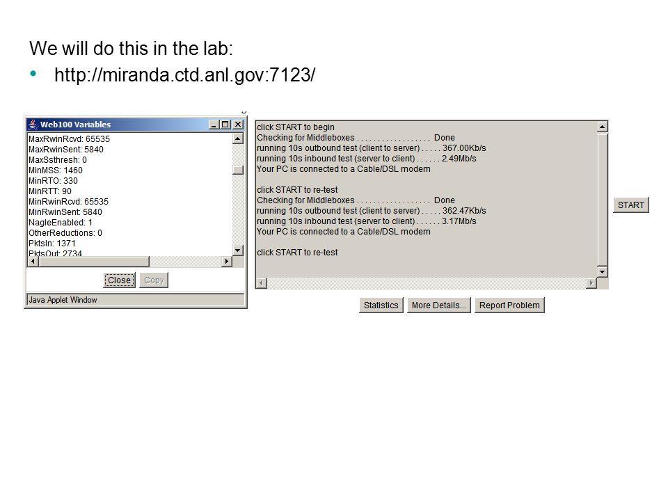
Using a browser go to this link and click on start:

95
More on TCP Sequence Numbers and Acknowledgements

96
The sequence and acknowledgment numbers are directional, which means that the communication occurs in both directions. The figure illustrates the communication going in one direction. The sequence and acknowledgments take place with the sender on the right. TCP provides full-duplex service, which means data can be flowing in each direction, independent of the other direction. Window sizes, sequence numbers and acknowledgment numbers are independent of each other’s data flow.

97
We will do this in the lab:
98
Viewing Receive Window Sizes in Ethereal
The TCP Receive Window size is the amount of receive data (in bytes) that can be buffered by this host, at one time on a connection. The other (sending) host can send only that amount of data before getting an acknowledgment and window update from this (the receiving) host.
 that can be buffered by this host, at one time on a connection. The other (sending) host can send only that amount of data before getting an acknowledgment and window update from this (the receiving) host.")
99
Viewing the Send Window Sizes in Ethereal
The TCP Receive Window size of the other host. How much data (in bytes) that can be sent by this host before receiving an acknowledgement from the other host.
 that can be sent by this host before receiving an acknowledgement from the other host.")
100
Ch.11 – TCP/IP Transport and Application Layers

Similar presentations


>")


>")

>")


