Download presentation
Presentation is loading. Please wait.

1
Operational Amplifiers

4
Chapter 14. Operational Amplifiers

5
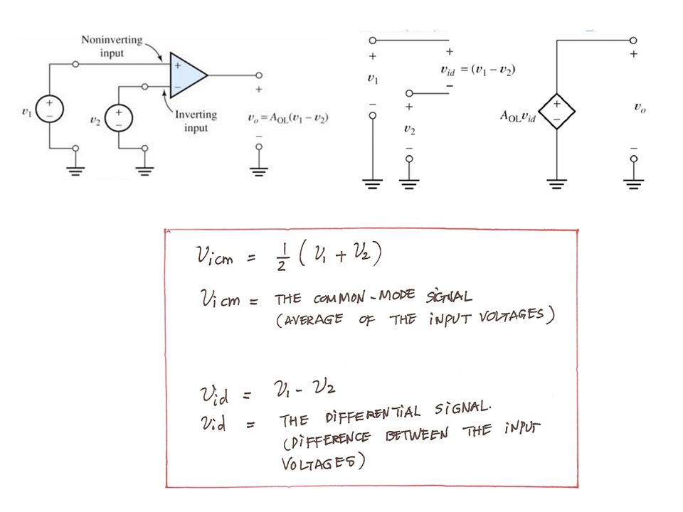
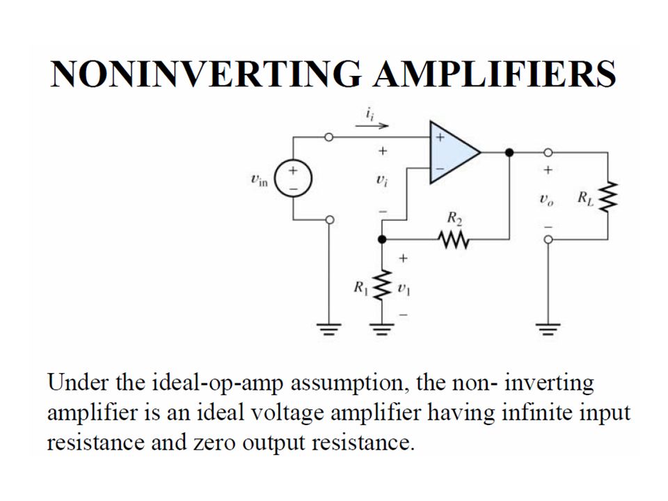
Operational Amplifiers Integrated circuit, also known as op amp. Wide range of applications. Ideal operational amplifier : - inverting and non-inverting input terminals. - common mode signal & differential mode signal - infinite input impedances - zero output impedance - very large open –loop gain.

8
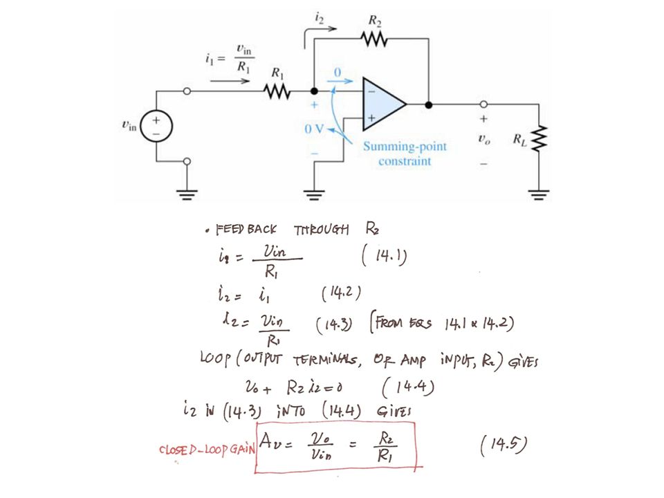
14.2 Inverting amplifiers

11
Example 14.1 : Analysis of an inverting amplifier

25
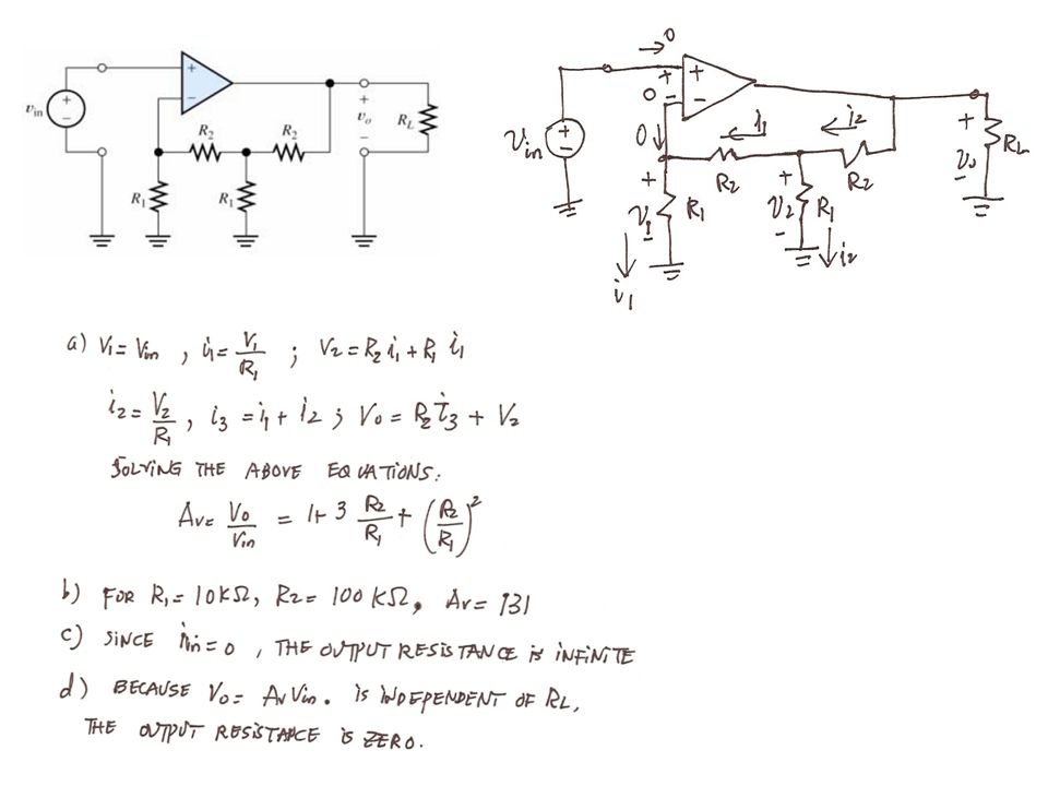
Exercise 14-17

30
Exercise 14-18

32
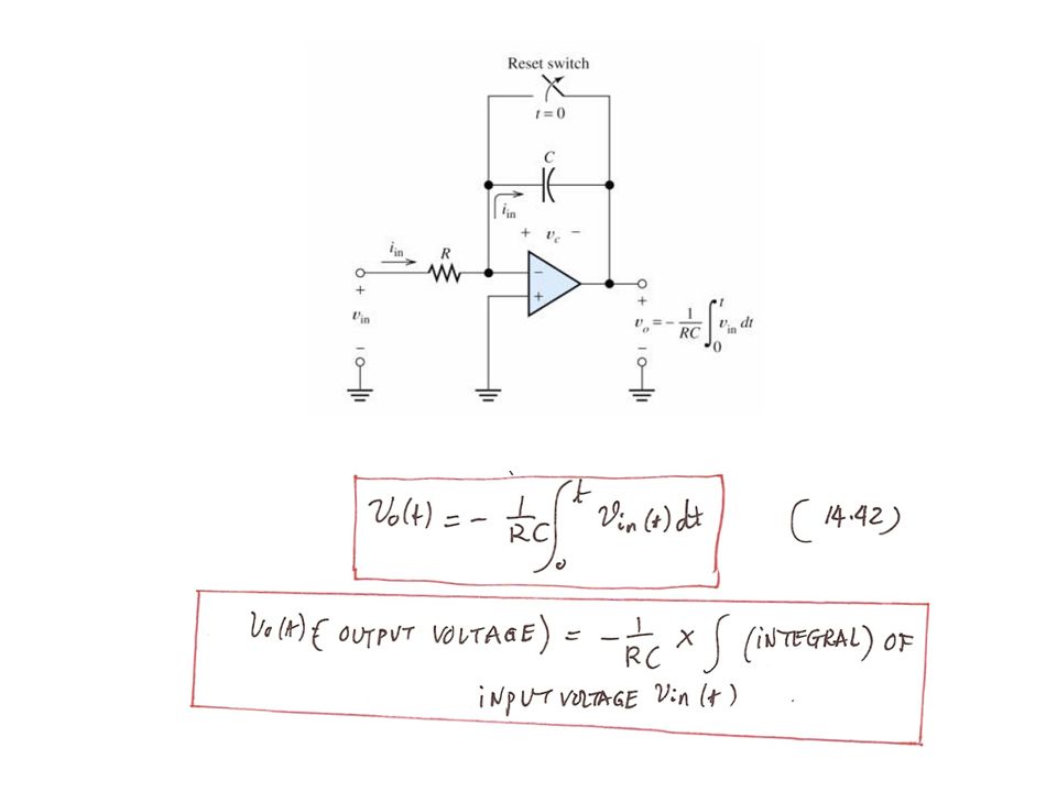
Differentiator Circuit

33
Active Filters Produce bandpass and bandreject filters without using inductors. Inductors are usually large, heavy, costly and generate electromagnetic field. Fewer components Transfer function is insentitive to component tolerances. Allow a wide range of transfer functions. Inappropriate for monolithic fabrication.

34
Fig. 12.1.2 Filter Types. Fig. 12.2 Ideal transmission characteristics of the four major filter types : (a) low pass (LP), (b) high pass (HP), (c ) bandpass (BP) and (d) bandstop (BS).
 low pass (LP), (b) high pass (HP), (c ) bandpass (BP) and (d) bandstop (BS)..")
35
Low –pass filter

37
Bode Plots Example 1

40
Bode Plots Example 2

Similar presentations


 for applications.>")


 Dr. Holbert April 3, 2006.>")


 Discussion D3.1.>")
 Circuits with Op-Amps (3.3) Prof. Phillips February 19, 2003.>")


 The open-loop gain, A v, is infinite. 2) The current into the inputs are zero.>")
>")
