Download presentation
Presentation is loading. Please wait.

1
Signamax Structured Cabling Seminar

2
INTRODUCTION

3
Generic Cabling Systems Evolution history: –60s, 70s, and 80s –Balanced and unbalanced transmission media –First adapters –Ethernet, Token Ring … –IBM, Cabletron, Bay Networks –Category 3 UTP, IBM Type I … –UDC, BNC, DB9, DB15, DB25 … –TIA/EIA (1985) –1991: ANSI/TIA/EIA-568 –ISO/IEC 11801, CENELEC EN 50173 … –First structured cabling systems
 –1991: ANSI/TIA/EIA-568 –ISO/IEC 11801, CENELEC EN … –First structured cabling systems")
4
Why structured cabling? Major risks connected with non-standard cabling: –Network performance is lower than the one specified by the standards –High cost of making changes to the system (the so-called MAC – Moves, Adds, Changes procedures) –Inability to support new technologies
 –Inability to support new technologies.")
5
Why structured cabling? As the principles of structured cabling design and installation become increasingly recognized, the installed network equipment becomes less and less expensive and the efficiency of data transmission grows exponentially The structured cabling system has been the basis for information network as long as it exists. It is a foundation, which enables all business applications A well designed, assembled, and maintained cabling system reduces maintenance costs at all stages of its lifetime

6
What is structured cabling? ISO/IEC 11801 definition of structured cabling: –“Generic cabling – a structured telecommunications cabling system, capable of supporting a wide range of applications. Generic cabling can be installed without prior knowledge of the required applications. Application specific hardware is not a part of generic cabling.”

7
What is Structured Cabling? Structured Cabling –is not a telephone network –is not a data network –is not a cable TV network –is not a video surveillance network –is not a BMS, FLS, etc. network Structured Cabling – integrated building engineering infrastructure (upon which all listed above networks can be built)
.")
8
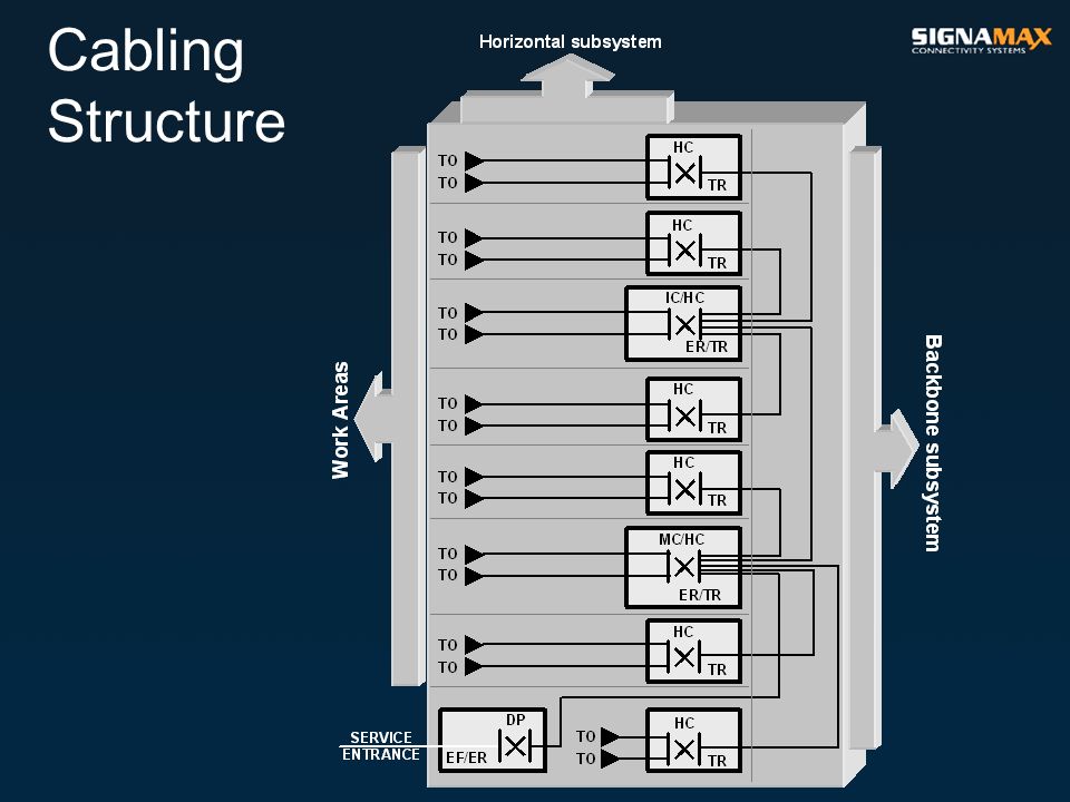
Cabling Structure Generic telecommunications cabling system structure includes the following subsystems and additional elements: –Horizontal subsystem –Backbone subsystem –Work Area –Telecommunications Room –Equipment Room –Entrance Facility –Administration

9
Functional elements Generic telecommunications cabling system consists of the following functional elements: –Main Cross-connect (MC) –Level I Backbone subsystem cable –Intermediate Cross-connect (IC) –Level II Backbone subsystem cable –Horizontal Cross-connect (HC) –Horizontal subsystem cable –Consolidation Point (CP) –Multiuser Telecommunications Outlet Assembly (MuTOA or MuTO) –Telecommunications Outlet (TO) Groups of these functional elements are connected together to form cabling subsystems
 –Level I Backbone subsystem cable –Intermediate Cross-connect (IC) –Level II Backbone subsystem cable –Horizontal Cross-connect (HC) –Horizontal subsystem cable –Consolidation Point (CP) –Multiuser Telecommunications Outlet Assembly (MuTOA or MuTO) –Telecommunications Outlet (TO) Groups of these functional elements are connected together to form cabling subsystems")
10
INTERBUILDING (CAMPUS) BACKBONE SUBSYSTEM BUILDING B IC ER/EF HC TR HC TR TO WA HC TR IC ER/EF HC TR HC TR TO WA BUILDING C IC ER/EF HC TR HC TR HC TR TO WA BUILDING D HC TR IC ER/EF HC TR HC TR TO WA BUILDING E HC TR TO WA INTRABUILDING BACKBONE SUBSYSTEM HORIZONTAL SUBSYSTEM SERVICE ENTRANCE LEVEL II BUILDING A IC ER LEVEL I HC TR HC TR DP EF MC ER/EF ER Cabling Structure
 BACKBONE SUBSYSTEM BUILDING B IC ER/EF HC TR HC TR TO WA HC TR IC ER/EF HC TR HC TR TO WA BUILDING C IC ER/EF HC TR HC TR HC TR TO WA BUILDING D HC TR IC ER/EF HC TR HC TR TO WA BUILDING E HC TR TO WA INTRABUILDING BACKBONE SUBSYSTEM HORIZONTAL SUBSYSTEM SERVICE ENTRANCE LEVEL II BUILDING A IC ER LEVEL I HC TR HC TR DP EF MC ER/EF ER Cabling Structure")
12
Subsystems Structured cabling schemes consist of three cabling subsystems: –Level I Backbone –Level II Backbone –Horizontal cabling The cabling subsystems are connected together to create a generic cabling structure. The cross-connects provide the means to configure the cabling to support different topologies like bus, star and ring

13
Level I Backbone Subsystem The level I Backbone cabling subsystem includes –the Level I Backbone cables; –jumpers and patch cords in the Main Cross-connect; –the connecting hardware on which the Level I Backbone cables are terminated (at both the Main and Intermediate Cross-connects)
")
14
Level II Backbone Subsystem The Level II Backbone cabling subsystem includes –the Level II Backbone cables; –jumpers and patch cords in the Intermediate Cross-connect; –the connecting hardware on which the Level II Backbone cables are terminated (at both the Intermediate and Horizontal Cross-connects)
")
15
Horizontal Subsystem The Horizontal cabling subsystem includes –the Horizontal subsystem cables –any cross-connections to application specific equipment at Horizontal Cross-connect –the mechanical termination of the Horizontal subsystem cables at the Horizontal Cross-connect including the connecting hardware –the mechanical termination of the Horizontal subsystem cables at the Telecommunications Outlet –a Consolidation Point (optional)
")
16
Interconnection of Subsystems Hierarchical structure

17
Interconnection of Subsystems Cross-connects shall be located in –Telecommunications Rooms –Equipment Rooms –Entrance Facilities

18
Channel & Permanent Link Structured cabling consist of Channels and Permanent Links. The transmission performance of structured cabling between specific interfaces is detailed in terms of the Channel and the Permanent Link

19
Channel & Permanent Link The Channel is the transmission path between active equipment and the terminal equipment. For the purposes of testing, the Channel does not include the mated connection at the IT equipment.

20
Channel & Permanent Link The Permanent Link is the transmission path between the mated connectors located at the ends of the installed cable in a cabling subsystem. The Permanent Link contains the mated connections located at the ends of the installed cabling

21
Dimensioning & configuring The number and type of subsystems that are part of a generic cabling implementation depends on the geography and size of the campus or building, as well as on the user strategy. Generally there would be –one Main Cross-connect per campus –one Intermediate Cross-connect per building –one Horizontal Cross-connect per floor If the premises have only a single building, which is small enough to be served by a single Horizontal Cross-connect, a level I Backbone cabling subsystem is not required

22
Dimensioning & configuring There should be at least one Horizontal Cross-connect for every 1,000 m 2 (10,000 ft 2 ) of floor space reserved for offices If a floor area is over 1,000 m 2 (10,000 ft 2 ), additional Horizontal Cross-connects may be required to provide more effective service to the Work Area
 of floor space reserved for offices If a floor area is over 1,000 m 2 (10,000 ft 2 ), additional Horizontal Cross-connects may be required to provide more effective service to the Work Area")
23
Dimensioning & configuring A minimum of one Horizontal Cross-connect should be provided for every floor. If a floor contains few people (e.g. a lobby), this floor may be served from the Horizontal Cross- connect located on an adjacent floor. If a floor is sparsely populated (e.g. a lobby), it is permissible to serve this floor from the Horizontal Cross-connects located on an adjacent floor
, this floor may be served from the Horizontal Cross- connect located on an adjacent floor. If a floor is sparsely populated (e.g. a lobby), it is permissible to serve this floor from the Horizontal Cross-connects located on an adjacent floor.")
24
Dimensioning & configuring The functions of multiple cross-connects may be combined

25
Dimensioning & configuring In some conditions, for example for reasons of security or reliability, redundancy may be built into a cabling design. This might form the basis for the design of generic cabling for a building, providing some protection against such hazards as fire damage or the failure of the public network feeder cable

26
STRUCTURED CABLING COMPONENTS

27
TRANSMISSION MEDIA Twisted Pair

28
Transmission Performance The following transmission performance categories of cabling components are used in structured cabling: Category 6a – four-pair 100-Ohm unscreened twisted-pair (UTP) or screened twisted-pair (ScTP, FTP, S/FTP) cables whose transmission characteristics are specified up to 500 MHz Category 6 – four-pair 100-Ohm unscreened twisted-pair (UTP) or screened twisted-pair (ScTP, FTP, S/FTP) cables whose transmission characteristics are specified up to 250 MHz continued on next page
 or screened twisted-pair (ScTP, FTP, S/FTP) cables whose transmission characteristics are specified up to 500 MHz Category 6 – four-pair 100-Ohm unscreened twisted-pair (UTP) or screened twisted-pair (ScTP, FTP, S/FTP) cables whose transmission characteristics are specified up to 250 MHz continued on next page")
29
Transmission Performance Category 5e – four-pair 100-Ohm unscreened twisted-pair (UTP) or screened twisted-pair (ScTP, FTP, S/FTP) cables whose transmission characteristics are specified up to 100 MHz Category 5 – 100-Ohm unscreened twisted-pair (UTP) or screened twisted-pair (ScTP, FTP) multipair cables whose transmission characteristics are specified up to 100 MHz Category 3 – 100-Ohm unscreened twisted-pair (UTP) multipair cables whose transmission characteristics are specified up to 16 MHz
 or screened twisted-pair (ScTP, FTP, S/FTP) cables whose transmission characteristics are specified up to 100 MHz Category 5 – 100-Ohm unscreened twisted-pair (UTP) or screened twisted-pair (ScTP, FTP) multipair cables whose transmission characteristics are specified up to 100 MHz Category 3 – 100-Ohm unscreened twisted-pair (UTP) multipair cables whose transmission characteristics are specified up to 16 MHz")
30
TRANSMISSION MEDIA Optical Fiber

31
Transmission Performance Structured cabling optical fiber cable transmission performance: Fiber TypeWavelength Maximum Attenuation Bandwidth MM 62.5/125 (OM1) 850 nm3.5 dB/km200 MHz-km 1300 nm1.5 dB/km500 MHz-km MM 50/125 (OM2) 850 nm3.5 dB/km500 MHz-km 1300 nm1.5 dB/km500 MHz-km MM 50/125 (OM3) 850 nm3.5 dB/km1500 MHz-km 1300 nm1.5 dB/km500 MHz-km SM ISP (OS1) 1310 nm1.0 dB/km N/A 1550 nm1.0 dB/kmN/A SM OSP (OS1) 1310 nm0.5 dB/kmN/A 1550 nm0.5 dB/kmN/A
 850 nm3.5 dB/km200 MHz-km 1300 nm1.5 dB/km500 MHz-km MM 50/125 (OM2) 850 nm3.5 dB/km500 MHz-km 1300 nm1.5 dB/km500 MHz-km MM 50/125 (OM3) 850 nm3.5 dB/km1500 MHz-km 1300 nm1.5 dB/km500 MHz-km SM ISP (OS1) 1310 nm1.0 dB/km N/A 1550 nm1.0 dB/kmN/A SM OSP (OS1) 1310 nm0.5 dB/kmN/A 1550 nm0.5 dB/kmN/A")
32
CONNECTING HARDWARE Twisted Pair

33
Transmission Performance The following of connecting hardware transmission performance categories are used in structured cabling: Category 6a – four-pair 100-Ohm unscreened twisted-pair (UTP) or screened twisted-pair (ScTP, FTP, S/FTP) connecting hardware whose transmission characteristics are specified up to 500 MHz Category 6 – four-pair 100-Ohm unscreened twisted-pair (UTP) or screened twisted-pair (ScTP, FTP, S/FTP) connecting hardware whose transmission characteristics are specified up to 250 MHz continued on next page
 or screened twisted-pair (ScTP, FTP, S/FTP) connecting hardware whose transmission characteristics are specified up to 500 MHz Category 6 – four-pair 100-Ohm unscreened twisted-pair (UTP) or screened twisted-pair (ScTP, FTP, S/FTP) connecting hardware whose transmission characteristics are specified up to 250 MHz continued on next page")
34
Transmission Performance The following of connecting hardware transmission performance categories are used in structured cabling: Category 5e – four-pair 100-Ohm unscreened twisted-pair (UTP) or screened twisted-pair (ScTP, FTP, S/FTP) connecting hardware whose transmission characteristics are specified up to 100 MHz Category/level 1, 2, 3, 4, 5, 7, and 8 connecting hardware are not recognized as part of structured cabling
 or screened twisted-pair (ScTP, FTP, S/FTP) connecting hardware whose transmission characteristics are specified up to 100 MHz Category/level 1, 2, 3, 4, 5, 7, and 8 connecting hardware are not recognized as part of structured cabling")
35
CONNECTING HARDWARE Optical Fiber

36
Connectors and Adaptors Connector designs shall meet the requirements of the corresponding TIA FOCIS (Fiber Optic Connector Intermateability Standard) document The multimode connector and adapter or a visible portion of them are identified by the color beige The singlemode connector and adapter or a visible portion of them are identified by the color blue
 document The multimode connector and adapter or a visible portion of them are identified by the color beige The singlemode connector and adapter or a visible portion of them are identified by the color blue")
37
Splices Optical fiber splices used in structured cabling, fusion or mechanical, shall not exceed a maximum optical attenuation of 0.3 dB Optical fiber splices, fusion or mechanical used in structured cabling, shall have a minimum return loss of 20 dB for multimode, and 26 dB for singlemode

38
EQUIPMENT CABLES AND PATCH CORDS Twisted Pair

39
Transmission Performance The following categories of equipment and patch cords transmission performance are used in structured cabling: Category 6a – four-pair 100-Ohm unscreened twisted-pair (UTP) or screened twisted-pair (ScTP, FTP, S/FTP) equipment and patch cords whose transmission characteristics are specified up to 500 MHz Category 6 – four-pair 100-Ohm unscreened twisted-pair (UTP) or screened twisted-pair (ScTP, FTP, S/FTP) equipment and patch cords whose transmission characteristics are specified up to 250 MHz Category 5e – unshielded (UTP) and shielded (ScTP, FTP, S/FTP) 100-Ohm twisted-pair equipment and patch cords with the bandwidth up to 100 MHz
 or screened twisted-pair (ScTP, FTP, S/FTP) equipment and patch cords whose transmission characteristics are specified up to 500 MHz Category 6 – four-pair 100-Ohm unscreened twisted-pair (UTP) or screened twisted-pair (ScTP, FTP, S/FTP) equipment and patch cords whose transmission characteristics are specified up to 250 MHz Category 5e – unshielded (UTP) and shielded (ScTP, FTP, S/FTP) 100-Ohm twisted-pair equipment and patch cords with the bandwidth up to 100 MHz")
40
EQUIPMENT CABLES AND PATCH CORDS Optical Fiber

41
Optical Fiber Cords Optical fiber equipment and patch cords, whether they are used for cross-connection or interconnection to active equipment, shall have such orientation that Position A goes to Position B on one fiber, and Position B goes to Position A on the other fiber of the fiber pair

42
Optical Fiber Cords Each end of the optical fiber equipment and patch cord shall be identified to designate Position A and Position B if the connector can be separated into its simplex components For alternate connector designs employing latches, the latch defines the positioning in the same way as the keys For simplex connectors, the connector that plugs into the receiver shall be considered Position A, and the connector that plugs into the transmitter shall be considered Position B

43
HORIZONTAL SUBSYSTEM

44
Horizontal Subsystem

45
CABLING SYSTEM

46
Horizontal Subsystem The Horizontal cabling subsystem is the part of structured cabling that extends from the Work Area Telecommunications Outlet to the Horizontal Cross-connect in the Telecommunications Room

47
Horizontal Subsystem The Horizontal cabling subsystem consists of –Horizontal subsystem cables –Telecommunications Outlet in the Work Area –connecting hardware at the Horizontal Cross-connect (interconnect or cross-connect) –any cross-connections to application specific equipment at the Horizontal Cross-connect –Consolidation Point (optional) –Multi-user Telecommunications Outlet (optional)
 –any cross-connections to application specific equipment at the Horizontal Cross-connect –Consolidation Point (optional) –Multi-user Telecommunications Outlet (optional)")
48
Topology TO CP WA TR FD (HC)
")
49
TELECOMMUNICATIONS PATHWAYS AND SPACES

50
Pathways and Spaces Horizontal subsystem pathways are facilities for the installation of telecommunications cable from the Telecommunications Room to the Work Area Telecommunications Outlet. Horizontal pathways encompass: –Underfloor pathways –Access floor –Conduit –Tray and wireway –Ceiling pathways –Perimeter pathways –Furniture pathways

51
BACKBONE SUBSYSTEM

52
Backbone Subsystem

53
CABLING SYSTEM

54
Backbone Subsystem The Backbone cabling subsystem is based on cabling segments, which link such connection centers as Main Cross-Connect, Intermediate Cross-connects, and Horizontal Cross-connects. In these centers Backbone subsystem links are connected with each other thereby forming Backbone subsystem channels that are used to distribute telecommunications services (voice, data, image, etc) to the Horizontal cabling subsystem Backbone cabling subsystem also includes cabling between buildings
 to the Horizontal cabling subsystem Backbone cabling subsystem also includes cabling between buildings.")
55
Backbone Subsystem The Backbone cabling subsystem consists of the following elements: –Main Cross-connect (MC) –Intermediate Cross-connect(s) (IC) –Horizontal Cross-connect(s) (HC) –Level I Backbone subsystem connecting MC with IC(s) or with HC(s) –Level II Backbone subsystem connecting IC(s) with HC(s) –Backbone cabling segments connecting Entrance Facility (EF) with MC or with IC(s) –Patch cords connecting the segments of the Backbone subsystem in the MC and IC(s)
 –Intermediate Cross-connect(s) (IC) –Horizontal Cross-connect(s) (HC) –Level I Backbone subsystem connecting MC with IC(s) or with HC(s) –Level II Backbone subsystem connecting IC(s) with HC(s) –Backbone cabling segments connecting Entrance Facility (EF) with MC or with IC(s) –Patch cords connecting the segments of the Backbone subsystem in the MC and IC(s)")
56
Star Topology

57
TELECOMMUNICATIONS PATHWAYS AND SPACES

58
Pathways and Spaces Backbone pathways consist of intra- and interbuilding pathways Backbone pathways may be either vertical or horizontal Interbuilding backbone pathways extend between buildings Intrabuilding backbone pathways are contained within a building

59
Pathways and Spaces One or more backbone facilities may exist within a building A backbone facility is generally formed by vertically stacking teecommunications closets with floor openings between them Tie pathways may also exist to install backbone media between telecommunications closets on the same floor

60
Pathways and Spaces Intra-building Backbone pathways encompass: –Underfloor pathways –Access floor –Conduit –Tray and wireway –Ceiling pathways –Perimeter pathways –Furniture pathways

61
Pathways and Spaces Inter-building Backbone pathways encompass : –Underground –Tunnels –Aerial

62
WORK AREA WA

63
Work Area

64
Work Areas are those spaces in a building where occupants interact with their telecommunications devices Work Area elements are situated between the Horizontal cabling system end point on the Telecommunications Outlet and Work Area active equipment The Work Area cabling system efficiency has a great impact on the distribution system operation The special feature of the Work Area cabling system is its versatility and ability to introduce changes easily

65
Work Area Work Area elements are: –Telecommunications Outlet or Multiuser Telecommunications Outlet –Equipment cables (cords) –Adapters, converters, couplers/splitters –Telecommunications equipment (telephones, computers, modems, terminals, etc.) Active telecommunications equipment and adapters (converters, couplers) are not considered part of the telecommunications cabling system and are not included into structured cabling
 –Adapters, converters, couplers/splitters –Telecommunications equipment (telephones, computers, modems, terminals, etc.) Active telecommunications equipment and adapters (converters, couplers) are not considered part of the telecommunications cabling system and are not included into structured cabling")
66
CABLING SYSTEM

67
Telecommunications Outlet Telecommunications Outlet/connector is a fixed connecting device where the horizontal cable terminates The Telecommunications Outlet/connector provides the interface to the Work Area cabling The Telecommunications Outlet/connector in the Work Area is the point at which end-user equipment "plugs into" the building telecommunications utility formed by the pathway, space, and building cabling system The Telecommunications Outlet/connector at the same time is an element of the Work Area and Horizontal subsystem

68
TELECOMMUNICATIONS PATHWAYS AND SPACES

69
Outlet Mount Box The mounting box of the Telecommunications Outlet is an intermediate element between the Horizontal subsystem cable and the Work Area cable The following are the most widely used ways to install the mounting boxes: –in or on the wall (or on any surface applicable for mounting) –in the perimetral pathway (cable raceway) –in the furniture pathway –on the flexible hose or conduit
 –in the perimetral pathway (cable raceway) –in the furniture pathway –on the flexible hose or conduit")
70
TELECOM ROOM TR

71
Telecommunications Room

72
Telecommunications Rooms (TRs) offer many different functions to the cabling system and are often considered as a distinct subsystem within the hierarchical cabling system The most important function of a Telecommunications Room is the termination of Horizontal and Backbone subsystem cables to compatible connecting hardware A Telecommunications Room may also include the Intermediate Cross-connect or the Main Cross-connect for different parts of the Backbone cabling subsystem
 offer many different functions to the cabling system and are often considered as a distinct subsystem within the hierarchical cabling system The most important function of a Telecommunications Room is the termination of Horizontal and Backbone subsystem cables to compatible connecting hardware A Telecommunications Room may also include the Intermediate Cross-connect or the Main Cross-connect for different parts of the Backbone cabling subsystem")
73
Telecommunications Room A Telecommunications Room provides the means for administration and routing of the equipment cables/cords from the Horizontal Cross-connect to the telecommunications equipment In some cases, the Demarcation Point and associated protection apparatus may also be located in the Telecommunications Room A Telecommunications Room also provides a controlled environment to house telecommunications equipment, connecting hardware, and splice closures serving a part of the building

74
EQUIPMENT ROOM ER

75
Equipment Room

76
The main function of the telecommunications Equipment Room is to provide a specially equipped area to terminate Backbone subsystem cables on connecting hardware of the Main and Intermediate Cross-connects Equipment Rooms (ERs) are considered different from Telecommunications Rooms because of the nature or complexity of the equipment contained in them An Equipment Room may provide any or all of the functions of a Telecommunications Room or Entrance Facility
 are considered different from Telecommunications Rooms because of the nature or complexity of the equipment contained in them An Equipment Room may provide any or all of the functions of a Telecommunications Room or Entrance Facility")
77
Equipment Room An Equipment Room provides a controlled environment to house telecommunications equipment, connecting hardware, splice closures, grounding and bonding facilities, and protection apparatus where applicable An Equipment Room may also house equipment terminations (and may contain Horizontal subsystem terminations for a part of the building) In many cases, the Equipment Room has access provider trunk terminations, premises network terminations, Demarcation Point (DP), and auxiliary terminations
 In many cases, the Equipment Room has access provider trunk terminations, premises network terminations, Demarcation Point (DP), and auxiliary terminations")
78
ENTRANCE FACILITY EF

79
Entrance Facility

80
The Entrance Facility (EF) consists of the telecommunications service entrance to the building, including the entrance through the building wall, and continuing to the entrance room or space The Entrance Facility may contain the Backbone pathways that connect to the Main or Intermediate Cross-connect and to other buildings in campus situations Antenna entrances may also constitute part of the Entrance Facility
 consists of the telecommunications service entrance to the building, including the entrance through the building wall, and continuing to the entrance room or space The Entrance Facility may contain the Backbone pathways that connect to the Main or Intermediate Cross-connect and to other buildings in campus situations Antenna entrances may also constitute part of the Entrance Facility")
81
Entrance Facility The Entrance Facility includes the cables, connecting hardware, protection devices, and other equipment required to connect the outside plant facilities to the premises cabling The Demarcation Point (DP) between the regulated access providers and the customer premises cabling may be part of the Entrance Facility
 between the regulated access providers and the customer premises cabling may be part of the Entrance Facility")
82
CABLING SYSTEM INSTALLATION

83
Installation Quality The quality of installation is the most serious problem in implementation of the telecommunications cabling systems designed for the high-speed applications support There is a special system of requirements and conditions to the installation of the cabling systems to preserve the primary transmission characteristics of individual components within the links, channels, and systems Whereas the rules of installation are the methods and accuracy of the component connections and cable organization and routing, the cabling rules are an important factor of the system capacity, simplifying the operation of the installed cabling systems

84
Installation Quality Significant reduction of the signal distortion may be achieved by the observance of the following requirements: –Usage of special methods of the cable preparation –Termination of the transmission media at the connecting hardware according to the manufacturer’s instructions –Ordered arrangement of the cable bundles –Correct spatial orientation of the connecting hardware –Observance of the installation rules and manufacturer’s requirements to the installation of the telecommunications connecting hardware.

85
Installation Quality The common law made by the standards is “The installed twisted-pair cabling system shall be classified by the link or channel component performance showing the worst transmission characteristics” Cat6 + Cat6 + Cat6 + Cat6 + Cat6 + Cat6 + Cat6 + Cat6 + Cat3 = Cat3 !!! This classification does not depend on the obtained field test results

86
CABLING SYSTEM ADMINISTRATION

87
Administration Concept

88
Labeling Labeling means marking of an element of the telecommunications infrastructure with an identifier and any other relevant information (optional)
")
89
Records A record means collecting information about or related to a specific element of the telecommunications infrastructure

90
Linkages Linkages mean the logical connections between identifiers and records In addition, a linkage between the records is established when one of the identifiers included in the record points to the other record Infrastructural records may be also linked to some other records (for example, databases of employees, an active equipment, data transmission systems, etc.) not included in the scope of this Manual Pathways Spaces Connecting Hardware Connecting Hardware Positions Bonding and Grounding System Elements Pathways Spaces Connecting Hardware Connecting Hardware Positions Bonding and Grounding System Elements Cable Record
 not included in the scope of this Manual Pathways Spaces Connecting Hardware Connecting Hardware Positions Bonding and Grounding System Elements Pathways Spaces Connecting Hardware Connecting Hardware Positions Bonding and Grounding System Elements Cable Record")
91
Reports The information selected from the various telecommunications infrastructural records is presented in reports The reports may be generated from a single set of records or several sets of interlinked records It may be preferred that the information from these reports is presented in several different formats

92
Drawings Drawings are used to illustrate different stages of telecommunications infrastructural design and installation

93
Work Orders Work orders are used for documentation of the operations required to introduce modifications affecting the telecommunications infrastructure A work order may involve: –Spaces –Pathways –Cables –Splices –Connecting Hardware –Connecting Hardware Positions –Bonding and Grounding Elements

94
LABELING

95
Labels Based on the attachment method, labels may be divided by the following categories: –Insert –Adhesive –Other

96
Insert Labels An insert label shall be securely fastened in place under the normal operating conditions and application, which the labeled infrastructural element is exposed to

97
Adhesive Labels When selecting adhesive labels, attention should be given to choosing material substrates designed for use on the specific surfaces to which the labels are to be attached In harsh environments, sleeving or tagging may be more suitable for cable marking Labels for elements where the label is essentially flat should be carefully selected so that the adhesive is appropriate for the element surface

98
CABLING SYSTEM CERTIFICATION TESTING

99
TWISTED-PAIR CABLING TESTING

100
General This section determines the characteristics of field test instruments, test methods, test configurations and minimum transmission requirements for a structured cabling based on 100-Ohm twisted-pair cable and connecting hardware The requirements are aimed at field-testing of installed twisted-pair cabling Channels/Permanent Links using field test instruments

101
TEST CONFIGURATIONS

102
Test Configurations Certification testing may be performed for either of two or both models of the cabling system: –Channel –Permanent Link

103
TEST PARAMETERS

104
ParameterCategory 5eCategory 6Category 6A 1 Wire map (T568A/T568B) Screen/shield continuity 2 Length ( L ) 3 Insertion loss ( IL ) 4 Pair-to-pair near-end crosstalk ( NEXT ) loss 5 Power sum near-end crosstalk ( PSNEXT ) loss 6 Pair-to-pair equal-level far-end crosstalk ( ELFEXT ) loss Pair-to-pair attenuation-to crosstalk ratio far end ( ACRF ) 7 Power sum equal-level far-end crosstalk ( PSELFEXT ) loss Power sum attenuation-to crosstalk ratio far end ( PSACRF ) 8 Alien near-end crosstalk ( ANEXT ) loss 9 Alien far-end crosstalk ( AFEXT ) loss 10 Power sum alien near-end crosstalk ( PSANEXT ) loss 11 Average power sum alien near-end crosstalk ( PSANEXT ) loss 12 Power sum attenuation to alien crosstalk ratio far-end ( PSAACRF ) 13 Average power sum attenuation to alien crosstalk ratio far-end ( PSAACRF ) 14 Return loss ( RL ) 15 Propagation delay ( PD ) 16 Propagation delay skew ( PDS )
 Screen/shield continuity 2 Length ( L ) 3 Insertion loss ( IL ) 4 Pair-to-pair near-end crosstalk ( NEXT ) loss 5 Power sum near-end crosstalk ( PSNEXT ) loss 6 Pair-to-pair equal-level far-end crosstalk ( ELFEXT ) loss Pair-to-pair attenuation-to crosstalk ratio far end ( ACRF ) 7 Power sum equal-level far-end crosstalk ( PSELFEXT ) loss Power sum attenuation-to crosstalk ratio far end ( PSACRF ) 8 Alien near-end crosstalk ( ANEXT ) loss 9 Alien far-end crosstalk ( AFEXT ) loss 10 Power sum alien near-end crosstalk ( PSANEXT ) loss 11 Average power sum alien near-end crosstalk ( PSANEXT ) loss 12 Power sum attenuation to alien crosstalk ratio far-end ( PSAACRF ) 13 Average power sum attenuation to alien crosstalk ratio far-end ( PSAACRF ) 14 Return loss ( RL ) 15 Propagation delay ( PD ) 16 Propagation delay skew ( PDS ) ")
105
FIELD TESTERS

106
Measurement Accuracy Minimum efficiency levels were defined for field testers: –Level IIe–category 3, 5, 5e cabling systems –Level III–category 3, 5, 5e, 6 cabling systems –Level IIIe–category 3, 5, 5e, 6, 6a cabling systems –Level IV–category 3, 5, 5e, 6, 6a, 7 cabling systems

107
TEST RESULTS

108
PASS/FAIL Criteria A Pass or Fail result for each parameter shall be determined by the permissible parameter limits The parameter test result shall be marked with an asterisk (*) when it is closer to the test limit than the measurement accuracy published by the field tester manufacturer for the Permanent Link and Channel
 when it is closer to the test limit than the measurement accuracy published by the field tester manufacturer for the Permanent Link and Channel")
109
PASS/FAIL Criteria 1 – Parameter allowable limit 2 – Measurement accuracy upper limit 3 – Measured parameter value 4 – Measurement accuracy lower limit 12341234

110
PASS/FAIL Criteria PASS: A measured value, the upper and the lower margins of the measurement accuracy of the field tester are below the permissible limit It gives rise to unambiguous interpretation of the result as positive The test result is positive, “passed testing”

111
PASS/FAIL Criteria PASS*: In spite of the fact that the measured value is below the permissible level, the upper margin of the measurement accuracy is below the permissible level, therefore there is a certain probability of permissible limit overrunning by the actual parameter value The test result is “conditionally passed testing”

112
PASS/FAIL Criteria FAIL*: In spite of the fact that the measured value is above the permissible level, the lower margin of the measurement accuracy is below the permissible level, therefore there is a certain probability of the actual parameter value to be kept within the permissible limits The test result is “conditionally failed testing”

113
PASS/FAIL Criteria FAIL: The measured value, the upper and the lower margins of the measurement accuracy of the field tester are above the permissible level It undoubtedly indicates the negative result The test result is negative, “failed testing”

114
PASS/FAIL Criteria An overall Pass or Fail condition shall be determined by the results of mandatory individual tests Any Fail or Fail* shall result in a general Fail In order to achieve a general Pass condition, any individual results must be Pass or Pass*

115
OPTICAL FIBER CABLING TESTING

116
General This section provides a description of the certification testing rules for optical fiber cabling systems based on multimode (62.5/125 and 50/125 micron) and singlemode transmission media
 and singlemode transmission media")
117
TEST CONFIGURATIONS

118
Optical Fiber Link An optical fiber link segment is the passive cabling, to include cable, connectors, and splices (if present), between two optical fiber connecting hardware termination points
, between two optical fiber connecting hardware termination points")
119
TEST PARAMETERS

120
Test Parameters Testing of the optical fiber components and systems includes measurements of several major characteristics For the certification testing of the majority of the optical fiber cabling systems, installed in the buildings and campus environments, it is usually sufficient to get the data on insertion loss and optical length Bandwidth (multimode) and dispersion (singlemode) are important performance parameters, however as they cannot be adversely affected by installation practices, they should be tested by the fiber manufacturer and do not require any field testing
 and dispersion (singlemode) are important performance parameters, however as they cannot be adversely affected by installation practices, they should be tested by the fiber manufacturer and do not require any field testing")
121
Insertion Loss Link insertion loss is based on the use of the One Reference Jumper Method specified by ANSI/TIA/EIA-526-14-A, Method B and ANSI/TIA/EIA-526-7, Method A.1 The test configuration of the link insertion loss does not include any active or passive devices other than cable, connectors and splices (i.e., optical bypass switches, couplers, repeaters or optical amplifiers)
")
122
FIELD TESTERS

123
Field Testers Insertion loss testing of optical fiber structured cabling can be performed with: –Power meter and light source or –Field testers including the optical fiber detectors within their sets, facilitating insertion loss tests

124
Field Testers Length testing of optical fiber structured can be performed with: –OTDR or –Field testers including the optical fiber detectors within their sets, facilitating the length tests or –Any other test optical fiber instrument for the optical fiber length measurement

Similar presentations


 Industrial Cabling Standard Pete Lockhart Anixter Manufacturing IT Forum Cleveland, Ohio May 20-21, 2008.>")


