Download presentation
Presentation is loading. Please wait.

1
SNAP technical design highlights 2010 2001 Supernova Acceleration Probe Development Configuration Launch Physics Discoveries Assembly Technology Physics Integration Engineering Michael Levi July 14, 2001

2
From Science Goals to Project Design Science Measure M and Measure w and w (z) Data Set Requirements Discoveries 3.8 mag before max Spectroscopy with S/N=10 at 15 Å bins Near-IR spectroscopy to 1.7 m Statistical Requirements Sufficient (~2000) numbers of SNe Ia …distributed in redshift …out to z < 1.7 Systematics Requirements Identified and proposed systematics: Measurements to eliminate / bound each one to +/–0.02 mag Satellite / Instrumentation Requirements ~2-meter mirrorDerived requirements: 1-square degree imager High Earth orbit Spectrograph ~50 Mb/sec bandwidth (0.35 m to 1.7 m)
 Data Set Requirements Discoveries 3.8 mag before max Spectroscopy with S/N=10 at 15 Å bins Near-IR spectroscopy to 1.7 m Statistical Requirements Sufficient (~2000) numbers of SNe Ia …distributed in redshift …out to z < 1.7 Systematics Requirements Identified and proposed systematics: Measurements to eliminate / bound each one to +/–0.02 mag Satellite / Instrumentation Requirements ~2-meter mirrorDerived requirements: 1-square degree imager High Earth orbit Spectrograph ~50 Mb/sec bandwidth (0.35 m to 1.7 m)")
3
l Minimum data set criteria: —Discovery within 2 days (rest frame) of explosion (peak + 3.8 magnitude), —Ten high S/N photometry points on lightcurve, —Lightcurve out to plateau (2.5 magnitude from peak), —High quality peak spectrophotometry l How to obtain both data quantity AND data quality? —Batch processing techniques with wide field -- large multiplex advantage, —Wide field imager designed to repeatedly observe an area of sky —Mostly preprogrammed observations, fixed fields —Very simple experiment, passive expt. Mission Requirements

4
SNAP a simple dedicated experiment to study the dark energy —Dedicated instrument, essentially no moving parts —Mirror: 2 meter aperture sensitive to light from distant SN —Optical Photometry: with 1°x 1° billion pixel mosaic camera, high-resistivity, rad- tolerant p-type CCDs sensitive over 0.35-1 m —IR photometry: 0.25 sq. degree FOV, HgCdTe array (1-1.7 m) —Integral field optical and IR spectroscopy: 0.35-1.7 m, 2”x2” FOV Mission Design
 —Integral field optical and IR spectroscopy: m, 2 x2 FOV Mission Design.")
5
Cut away View of Structure

6
Telescope Assembly Movie courtesy of Hytec

7
Edge Ray Spot Diagram (box = 1 pixel): Optical Solution: Primary Mirror diameter= 200 cm Secondary Mirror diameter= 42 cm Tertiary Mirror diameter=64 cm Observatory Parameters
: Optical Solution: Primary Mirror diameter= 200 cm Secondary Mirror diameter= 42 cm Tertiary Mirror diameter=64 cm Observatory Parameters")
8
Optical Train

9
Key requirements and issues —Dimensional stability —High specific stiffness (1g sag, acoustic response) —Stresses during launch —Design of supports Baseline technology —Multi-piece, fusion bonded, with egg-crate core —Meniscus shaped —Triangular core cells Material —Baseline = ULE Glass (Corning) Initial design for primary mirror substrate: 120 kg Primary Mirror Substrate
 —Stresses during launch —Design of supports Baseline technology —Multi-piece, fusion bonded, with egg-crate core —Meniscus shaped —Triangular core cells Material —Baseline = ULE Glass (Corning) Initial design for primary mirror substrate: 120 kg Primary Mirror Substrate")
10
Goddard Designed Spacecraft

11
Spacecraft Assembly Movie courtesy of Hytec

12
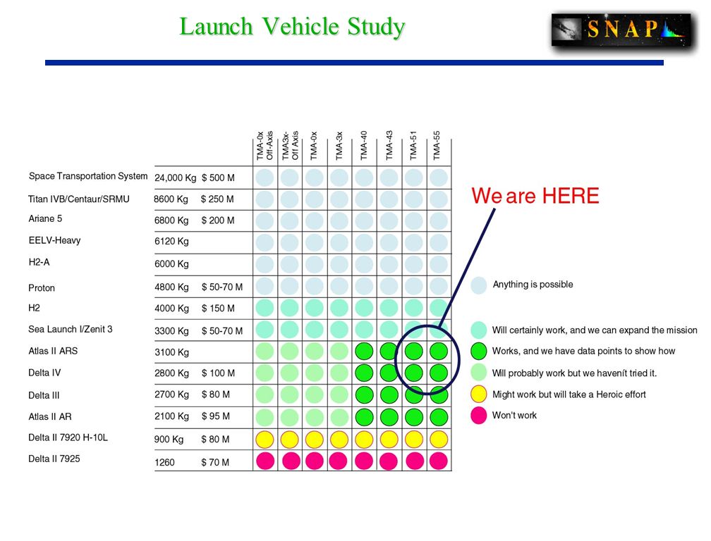
Launch Vehicle Study

14
Sea Launch Fairing

15
Orbit Trade-Study Feasibility & Trade-Study Selected Lunar Assist “Prometheus” Orbit 14 day orbit: 39 Re semi-major axis

16
Orbit Optimization Uses Lunar Assist to Achieve a 14 day Orbit, with a Delta III, Delta IV-M, Atlas III, or Sea Launch Zenit-3SL Launch Vehicle Good Overall Optimization of Mission Trade-offs Low Earth Albedo Provides Multiple Advantages: Minimum Thermal Change on Structure Reduces Demand on Attitude Control Minimum Thermal Change on Telescope – very stable PSF Excellent Telemetry, reduces risk on satellite Outside Radiation Belts Passive Cooling of Detectors Minimizes Stray Light MAP currently proving orbit concept

17
Three Ground Stations

18
Mission Operations Mission Operations Center (MOC) at Space Sciences Using Berkeley Ground Station Fully Automated System Tracks Multiple Spacecraft 11 meter dish at Space Sciences Laboratory Science Operations Center (SOC) closely tied to MOC Operations are Based on a Four Day Period Autonomous Operation of the Spacecraft Coincident Science Operations Center Review of Data with Build of Target List Upload Instrument Configuration for Next Period
 at Space Sciences Using Berkeley Ground Station Fully Automated System Tracks Multiple Spacecraft 11 meter dish at Space Sciences Laboratory Science Operations Center (SOC) closely tied to MOC Operations are Based on a Four Day Period Autonomous Operation of the Spacecraft Coincident Science Operations Center Review of Data with Build of Target List Upload Instrument Configuration for Next Period")
19
GigaCAM, a one billion pixel array l Approximately 1 billion pixels l ~132 Large format CCD detectors required l Larger than SDSS camera, smaller than H.E.P. Vertex Detector (1 m 2 ) l Approx. 5 times size of FAME (MiDEX)GigaCAM
 l Approx. 5 times size of FAME (MiDEX)GigaCAM.")
20
Camera Assembly Heat radiator Filter Wheel Folding Mirror Shield GigaCam

21
IR Enhanced Camera with Fixed Filter Set 25 HgCdTe 132 CCD’s 3 IR Filters 8 Visible Filters

22
Mosaic Packaging With precision CCD modules, precision baseplate, and adequate clearances designed in, the focal plane assemble is “plug and play.” 140 K plate attached to space radiator.

23
CCD Subassembly

24
Typical CCD’s

25
Silicon Absorption Length Photoactive region of standard CCD’s are 10-20 microns thick Photoactive region of LBNL CCD’s are 300 microns thick

26
High-Resistivity CCD’s Broad technology patent for high-resistivity CCD technology Better overall response than more costly “thinned” devices in use High-purity silicon has better radiation tolerance for space applications The CCD’s can be abutted on all four sides enabling very large mosaic arrays Measured Quantum Efficiency at Lick Observatory (R. Stover):
:.")
27
LBNL 2k x 2k results Image: 200 x 200 15 m LBNL CCD in Lick Nickel 1m. Spectrum: 800 x 1980 15 m LBNL CCD in NOAO KPNO spectrograph. Instrument at NOAO KPNO 2 nd semester 2001 (http://www.noao.edu)

28
LBNL 2k x 4k USAF test pattern. Trap sites found by pocket pumping. 1478 x 4784 10.5 m 1294 x 4186 12 m 2k x 4k 15 m

29
Measurement of PSF with pinhole mask Measurements at Lick Observatory

30
Measurement of PSF with pinhole mask Measurements at Lick Observatory

31
CCD Diffusion

32
Intra-pixel variation

33
Solar protons are damaging to CCDs. WFPC2 on HST developed losses up to 40% across its CCD due to radiation damage. Radiation testing is done at the LBNL 88” Cyclotron with 12 MeV protons. SNAP expected lifetime dose 5 x 10 9 protons/cm 2 Radiation Damage CTI is the charge transfer inefficiency Q = Q 0 (1-CTI)*N transfer N transfer ~ 2000 HST SNAP
*N transfer N transfer ~ 2000 HST SNAP.")
34
10.5 m Well Depth

35
Instrument Electronics Context

36
CDS – Correlated Double Samples is used for readout of the CCDs to achieve the required readout noise. Programmable gain receiver, dual-ramp architecture, and ADC buffer. HgCdTe compatible. ADC – 16-bit, 100 kHz equivalent conversion rate per CCD (could be a single muxed 400 kHz unit). Sequencer – Clock pattern generator supporting modes of operation: erase, expose, readout, idle. Clock drivers – Programmable amplitude and rise/fall times. Supports 4-corner or 2-corner readout. Bias and power generation – Provide switched, programmable large voltages for CCD and local power. Temperature monitoring – Local and remote. DAQ and instrument control interface – Path to data buffer memory, master timing, and configuration and control. Readout Electronics Concept
. Sequencer – Clock pattern generator supporting modes of operation: erase, expose, readout, idle. Clock drivers – Programmable amplitude and rise/fall times. Supports 4-corner or 2-corner readout. Bias and power generation – Provide switched, programmable large voltages for CCD and local power. Temperature monitoring – Local and remote. DAQ and instrument control interface – Path to data buffer memory, master timing, and configuration and control. Readout Electronics Concept.")
37
CDS ASIC

38
Shortwave HdCdTe Development Hubble Space Telescope Wide Field Camera 3 WFC-3 replaces WFPC-2 CCDs & IR HgCdTe array Ready for flight July 2003 1.7 m cut off 18 m pixel 1024 x 1024 format Hawaii-1R MUX Dark current consistent with thermoelectric cooling < 0.5 e/s at 150 K <0.05 e-/s at 140 K Expected QE > 50% 0.9-1.7 m Individual diodes show good QE Effective CdZnTe AR coating No hybrid device with simultaneous good dark current & QE WFC-3 IR NIC-2

39
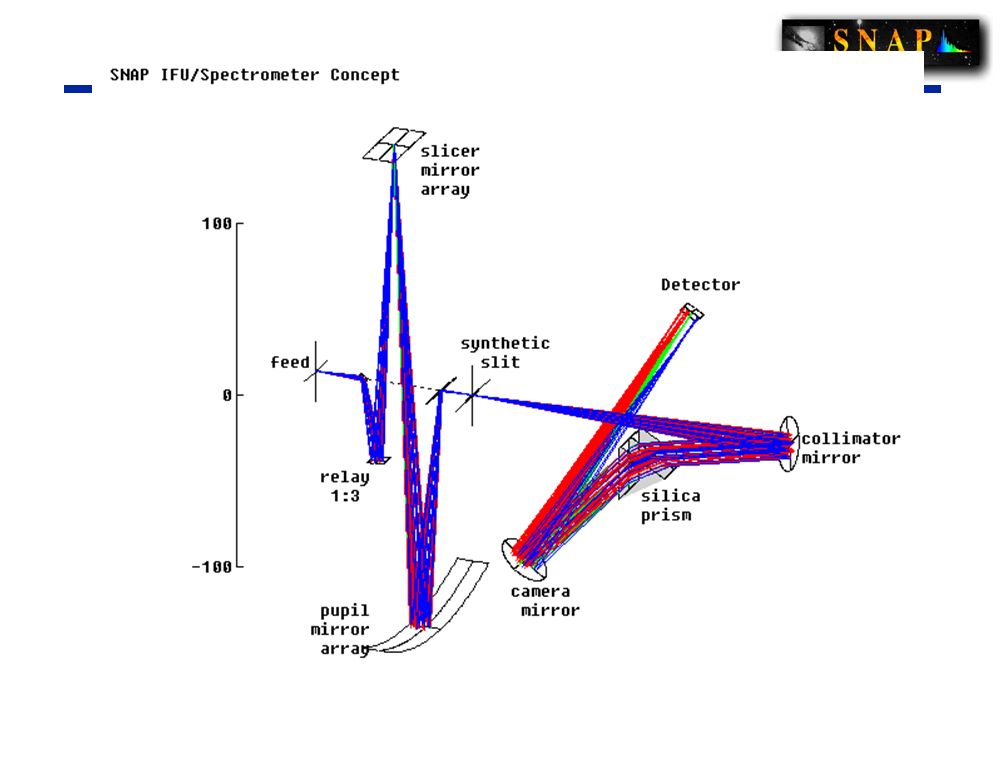
Spectroscopic Integral Field Unit Techniques

41
Current Work Areas Optical Telescope Assembly optics design, trade studies, risk assessment Instrument development Orbit analysis and study Structure design Thermal control system design Attitude Control System analysis and modeling Spacecraft systems refinement Integration and Test planning Data system layout Computational system definition

42
Technology readiness and issues NIR sensors HgCdTe stripped devices are begin developed for NGST and are ideal in our spectrograph. "Conventional" devices with appropriate wavelength cutoff are being developed for WFC3 and ESO. CCDs We have demonstrated radiation hardiness that is sufficient for the SNAP mission, but now need to extend to Co 60 and commercial devices Extrapolation of earlier measurements of diffusion's effect on PSF indicates we can get to the sub 4 micron level. Needs demonstration. Industrialization of CCD fabrication has produced useful devices. More wafers have just arrived. Detectors & electronics are the largest cost uncertainty. ASIC development is required. Filters – we are investigating three strategies for fixed filters. Suspending filters above sensors Gluing filters to sensors Direct deposition of filters onto sensors.

43
Technology readiness and issues On-board data handling We have opted to send all data to ground to simplify the flight hardware and to minimize the development of flight-worthy software. 50 Mbs telemetry, and continuous ground contact are required. Goddard has validated this approach. Calibration There is an active group investigating all aspects of calibration. Pointing The new generation HgCdTe multiplexor and readout IC support high rate readout of regions of interest for generating star guider information. Next generation attitude control systems may have sufficient pointing accuracy so that nothing special needs be done with the sensors. Telescope Thermal and stray light Software Data analysis pipeline architecture

44
Conclusion Fundamental science Lots of R&D going on right now Many areas that are uncovered or need very significant effort Collaboration still growing We need your help!

Similar presentations
 Scott Sandwith New.>")


 Arrays of pixels, each composed on a photodetector (photodiode), amplifier,>")


, ~2’x2’ FOV Detector sensitivity engineered to cut off above 1.7 micron,>")
 David Leckrone Senior Project Scientist for HST December 16, 2001.>")

 Natalia Kuznetsova Natalia Kuznetsova.>")


, ~2’x2’ FOV Detector.>")
, J. Balleza (IDTL),>")