Download presentation
Presentation is loading. Please wait.

1
Things to grab for this session (in priority order) Pencil Henderson, Perry, and Young text (Principles of Process Engineering) Calculator Eraser Scratch paper Units conversion chart Tables of fluid properties Moody diagram Pump affinity laws
 Pencil Henderson, Perry, and Young text (Principles of Process Engineering) Calculator Eraser Scratch paper Units conversion chart Tables of fluid properties Moody diagram Pump affinity laws")
2
Core Ag Engineering Principles – Session 1 Bernoulli’s Equation Pump Applications

3
Bernoulli’s Equation Hydrodynamics (the fluid is moving) Incompressible fluid (liquids and gases at low pressures) Therefore changes in fluid density are not considered
 Incompressible fluid (liquids and gases at low pressures) Therefore changes in fluid density are not considered")
4
Conservation of Mass If the rate of flow is constant at any point and there is no accumulation or depletion of fluid within the system, the principle of conservation of mass (where mass flow rate is in kg/s) requires:
 requires:")
5
For incompressible fluids – density remains constant and the equation becomes: Q is volumetric flow rate in m 3 /s A is cross-sectional area of pipe (m 2 ) and V is the velocity of the fluid in m/s
 and V is the velocity of the fluid in m/s")
6
Example Water is flowing in a 15 cm ID pipe at a velocity of 0.3 m/s. The pipe enlarges to an inside diameter of 30 cm. What is the velocity in the larger section, the volumetric flow rate, and the mass flow rate?

7
Example D 1 = 0.15 mD 2 = 0.3 m V 1 = 0.3 m/sV 2 = ? How do we find V 2 ?

8
Example D 1 = 15 cm IDD 2 = 30 cm ID V 1 = 0.3 m/sV 2 = ? We know A 1 V 1 = A 2 V 2

9
Answer V 2 = 0.075 m/s

10
What is the volumetric flow rate?

11
Volumetric flow rate = Q

13
What is the mass flow rate in the larger section of pipe?

14
Mass flow rate =

16
Bernoulli’s Theorem Since energy is neither created nor destroyed within the fluid system, the total energy of the fluid at one point in the system must equal the total energy at any other point plus any transfers of energy into or out of the system.

17
Bernoulli’s Theorem h = elevation of point 1 (m or ft) P 1 = pressure (Pa or psi) = specific weight of fluid v = velocity of fluid
 P 1 = pressure (Pa or psi) = specific weight of fluid v = velocity of fluid")
18
Bernoulli’s Theorem Special Cases When system is open to the atmosphere, then P=0 if reference pressure is atmospheric (can be one P or both P’s)
")
19
When one V refers to a storage tank and the other V refers to a pipe, then V of tank <<<< V pipe and assumed zero If no pump or fan is between the two points chosen, W=0

20
Find the total energy (ft) at B; assume flow is frictionless A B C 125’ 75’ 25’
 at B; assume flow is frictionless A B C 125’ 75’ 25’")
21
Example Why is total energy in units of ft? What are the typical units of energy? How do we start the problem?

22
Example Total Energy A = Total Energy B Total Energy B h A = 125’ = Total Energy B

23
Example Find the velocity at point C. 0

24
Try it yourself: pump 9’ 1’ x’ 1’ Water is pumped at the rate of 3 cfs through piping system shown. If the pump has a discharge pressure of 150 psig, to what elevation can the tank be raised? Assume the head loss due to friction is 10 feet.

25
Determining F for Pipes and Grain

26
Step 1 Determine Reynolds number Dynamic viscosity units Diameter of pipe Velocity Density of fluid

27
Reynolds numbers: < 2130 Laminar > 4000 Turbulent Affects what?

28
Reynolds numbers: < 2130 Laminar > 4000 Turbulent Affects what? The f in Darcy’s equation for friction loss in pipe Laminar: f = 64 / Re Turbulent: Colebrook equation or Moody diagram

29
Total F F = F pipe + F expansion + F expansion + F fittings

30
Darcy’s Formula

31
Where do you use relative roughness?

32
Relative roughness is a function of the pipe material; for turbulent flow it is a value needed to use the Moody diagram (ε/D) along with the Reynolds number
 along with the Reynolds number")
33
Example Find f if the relative roughness is 0.046 mm, pipe diameter is 5 cm, and the Reynolds number is 17312

34
Solution ε / D = 0.000046 m / 0.05 m = 0.00092 Re = 1.7 x 10 4 Re > 4000; turbulent flow – use Moody diagram

35
Find ε/D, move to left until hit dark black line – slide up line until intersect with Re #

36
Answer f = 0.0285

37
Energy Loss due to Fittings and Sudden Contractions

38
Energy Loss due to Sudden Enlargement

39
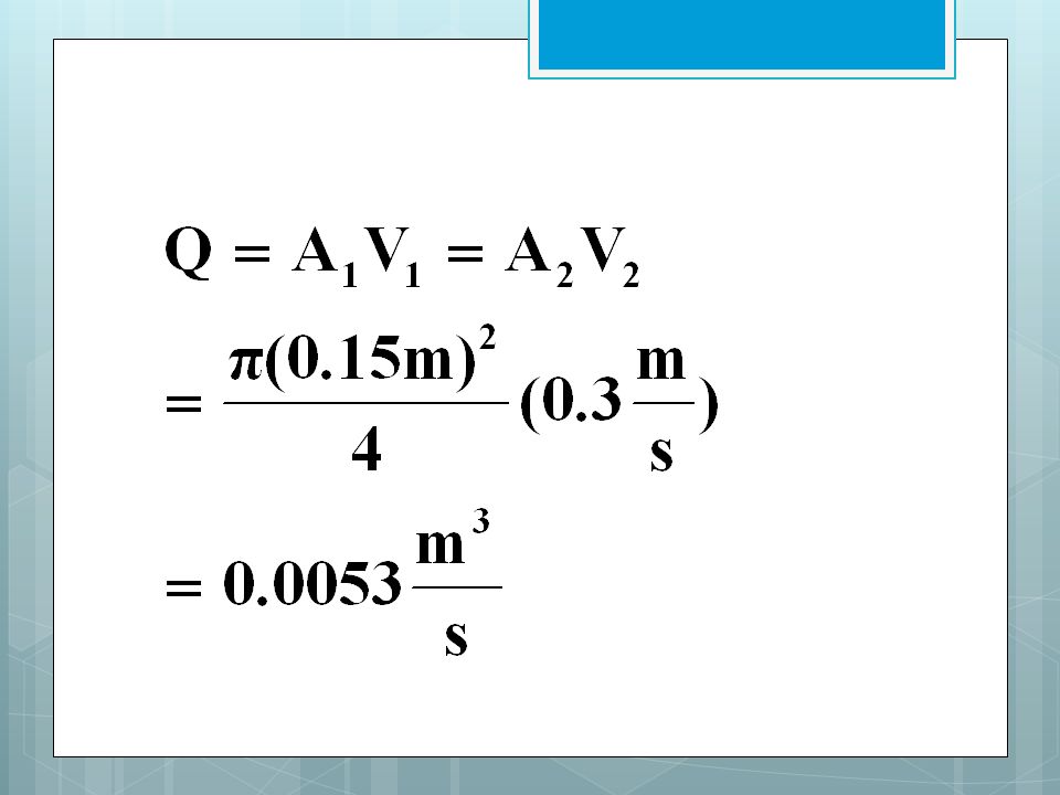
Example Milk at 20.2C is to be lifted 3.6 m through 10 m of sanitary pipe (2 cm ID pipe) that contains two Type A elbows. Milk in the lower reservoir enters the pipe through a type A entrance at the rate of 0.3 m 3 /min. Calculate F.

40
Step 1:

41
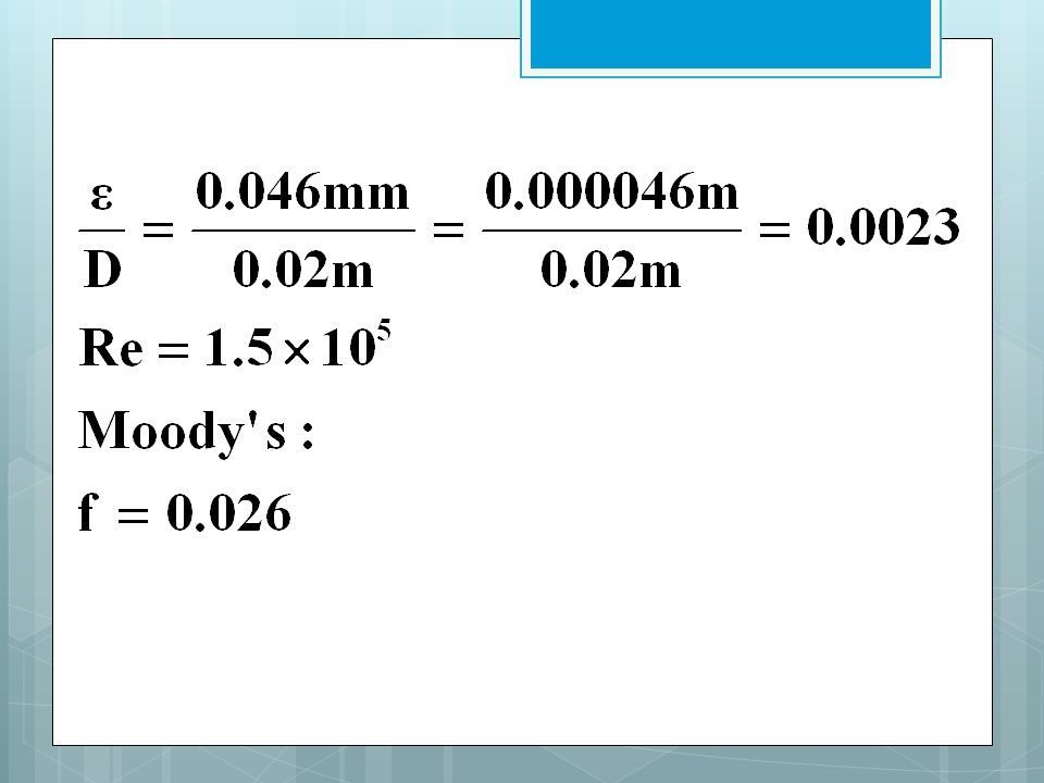
Step 1: Calculate Re number

42
Calculate v = ? Calculate v 2 / 2g, because we’ll need this a lot

44
What is viscosity? What is density?

45
Viscosity = 2.13 x 10 -3 Pa · s ρ = 1030 kg/m 3

46
So Re = 154,000

47
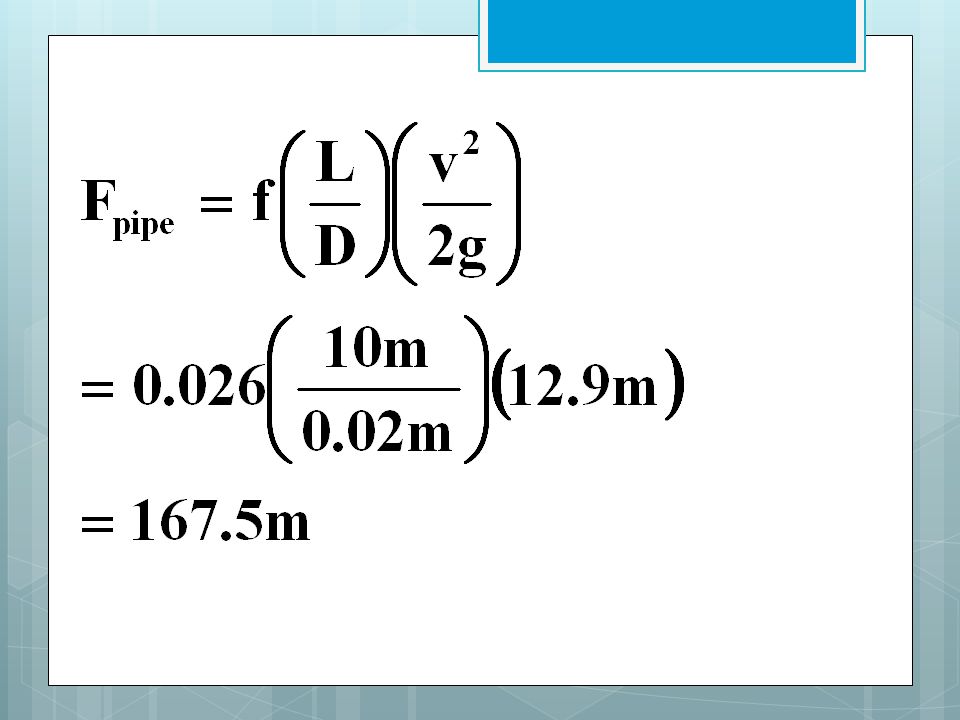
f = ? F pipe =

50
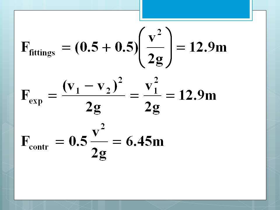
F fittings = F expansion = F contraction =

52
F total = 199.7 m

53
Try it yourself Find F for milk at 20.2 C flowing at 0.075 m 3 /min in sanitary tubing with a 4 cm ID through 20 m of pipe, with one type A elbow and one type A entrance. The milk flows from one reservoir into another.

54
Pump Applications

55
Power The power output of a pump is calculated by: W = work from pump (ft or m) Q = volumetric flow rate (ft 3 /s or m 3 /s) ρ = density g = gravity
 Q = volumetric flow rate (ft 3 /s or m 3 /s) ρ = density g = gravity")
56
System Characteristic Curves A system characteristic curve is calculated by solving Bernoulli’s theorem for many different Q’s and solving for W’s This curve tells us the input head required to move the fluid at that Q through that system

57
Example system characteristic curve

58
Pump Performance Curves Given by the manufacturer – plots total head against volumetric discharge rate Note: these curves are good for ONLY one speed, and one impeller diameter – to change speeds or diameters we need to use pump laws

59
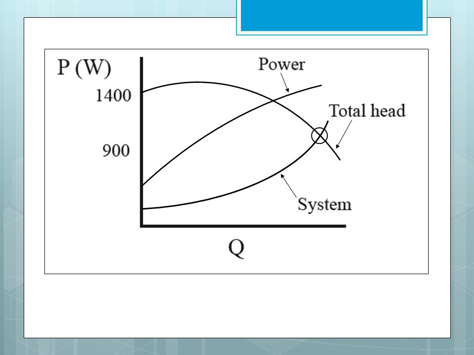
Efficiency Total head Power

60
Pump Operating Point Pump operating point is found by the intersection of pump performance curve and system characteristic curve

61
What volumetric flow rate will this pump discharge on this system?

62
Performance of centrifugal pumps while pumping water is used as standard for comparing pumps

63
To compare pumps at any other speed than that at which tests were conducted or to compare performance curves for geometrically similar pumps – use affinity laws

64
Pump Affinity Laws Q 1 /Q 2 =(N 1 /N 2 )(D 1 /D 2 ) 3 W 1 /W 2 =(N 1 /N 2 ) 2 (D 1 /D 2 ) 2 Po 1 /Po 2 =(N 1 /N 2 ) 3( D 1 /D 2 ) 5 (ρ 1 /ρ 2 )
(D 1 /D 2 ) 3 W 1 /W 2 =(N 1 /N 2 ) 2 (D 1 /D 2 ) 2 Po 1 /Po 2 =(N 1 /N 2 ) 3( D 1 /D 2 ) 5 (ρ 1 /ρ 2 )")
65
A pump is to be selected that is geometrically similar to the pump given in the performance curve below, and the same system. What D and N would give 0.005 m 3 /s against a head of 19.8 m? 900W 9m 1400W W 0.01 m 3 /s D = 17.8 cm N = 1760 rpm

66
What is the operating point of first pump? N 1 = 1760 D 1 = 17.8 cm Q 1 = 0.01 m 3 /s Q 2 = 0.005 m 3 /s W 1 = 9m W 2 = 19.8 m

67
Now we need to “map” to new pump on same system curve. Substitute into Solve for D 2

68
Q 1 /Q 2 =(N 1 /N 2 )(D 1 /D 2 ) 3 N 2 = N 1 (Q 2 /Q 1 )(D 1 /D 2 ) 3 N 2 = ?
(D 1 /D 2 ) 3 N 2 = N 1 (Q 2 /Q 1 )(D 1 /D 2 ) 3 N 2 =")
70
Try it yourself If the system used in the previous example was changed by removing a length of pipe and an elbow – what changes would that require you to make? Would N 1 change? D 1 ? Q 1 ? W 1 ? P 1 ? Which direction (greater or smaller) would “they” move if they change?
 would they move if they change .")
Similar presentations


 Chapter 9: FLOWS IN PIPE>")


