Download presentation
Presentation is loading. Please wait.

1
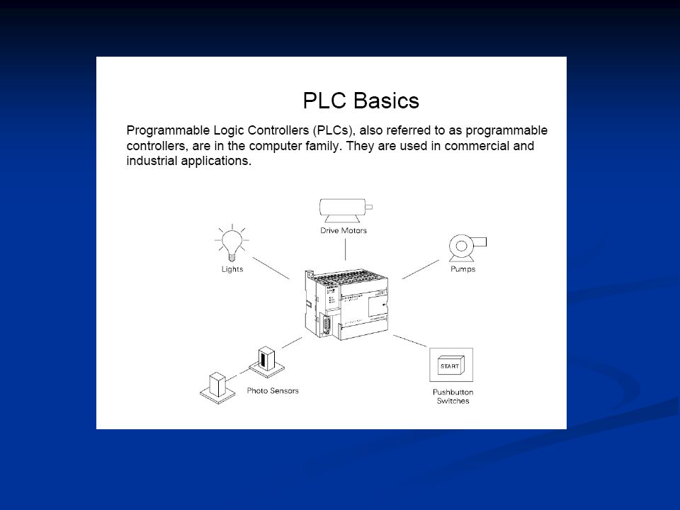
Definition of PLC A digitally operating electronic apparatus which uses a programming memory for the internal storage of instructions for implementing specific functions such as logic, sequencing, timing, counting and arithmetic to control through digital or analog modules, various types of machines or process.

2
PLC Programmable Logic Controllers
A PLC is a user-friendly, microprocessor-based that carries out control functions of many types. Its purpose is to monitor crucial process parameters and adjust process operations accordingly.

4
History of PLC Today, big unit PLC is at the low end.
When a few years the micro PLC entered the market, some thought that these devices had “bottom out” Now, nano PLC – generally defined as those with 16 or fewer I/O – are spreading. Some can fit into your shirt pocket.

5
History of PLC The first PLC evolved from conventional computers in the late 1960s. In 1970s, PLC programs are complicated and required a highly trained programmer to make the changes. It then improved for high-level language and become more understandable to more people.

6
History of PLC In the 1980s, the cost of microprocessors went down and PLC can be found in robotics, automation devices, CNC (computer numerical control), building energy and security control systems, home, medical equipments.
, building energy and security control systems, home, medical equipments.")
7
Leading Brands of PLC AMERICAN EUROPEAN Siemens Klockner & Mouller
Allen Bradley Gould Modicon Texas Instruments General Electric Westinghouse Cutter Hammer Square D EUROPEAN Siemens Klockner & Mouller Festo Telemechanique

8
Leading Brands of PLC JAPANESE Toshiba Omron Fanuc Mitsubishi

9
PLC Adv. & Disadvantages
Flexibility – one PLC for many machines Implementing Changes and Correcting Errors is easy Large Quantity of Contacts for each coil (Relay) Lower Cost – more functions and less expensive Pilot Running – can be pre-run and evaluated in the office. Speed of Operation – Relay can take an unacceptable amount of time to actuate
 Lower Cost – more functions and less expensive. Pilot Running – can be pre-run and evaluated in the office. Speed of Operation – Relay can take an unacceptable amount of time to actuate.")
10
PLC Adv. & Disadvantages
Security – program change cannot be make unless the PLC is properly unlocked. Ease of Changes - PLC can be reprogrammed quickly (DisAdv)Fixed Program Application – some applications are simple single-function applications. It does not pay to use a PLC (DisAdv) Environmental Considerations – High heat and vibration will limit their use
Fixed Program Application – some applications are simple single-function applications. It does not pay to use a PLC. (DisAdv) Environmental Considerations – High heat and vibration will limit their use.")
11
ADV of PLC Less wiring. Wiring between devices and relay contacts are done in the PLC program. Trouble shooting aids make programming easier and reduce downtime. Reliable components make these likely to operate for years before failure.

12
Tank Used to Mix Two Liquids
PLC APPLICATIONS Tank Used to Mix Two Liquids A B C FS MOTOR TIMER FLOAT SWITCH SOLENOIDS SOLENOID 1 -MINUTE 12

13
Tank Used to Mix Two Liquids
A tank is used to mix two liquids. The control circuit operates as follows: 1. When the start button is pressed, solenoids A and B energize. This permits the two liquids to begin filling the tank. 2. When the tank is filled, the float switch trips. This de-energizes solenoids A and B and starts the motor used to mix the liquids together. 3. The motor is permitted to run for one minute. After one minute has elapsed, the motor turns off and solenoid C energizes to drain the tank.

14
4. When the tank is empty, the float switch de-energizes solenoid C.
5. A stop button can be used to stop the process at any point. 6. If the motor becomes overloaded, the action of the entire circuit will stop. 7. Once the circuit has been energized it will continue to operate until it is manually stopped.

15
PLC SYSTEM CPU – include memory and micro-P
Programmer/Monitor – a device used to communicate with the circuit of the PLC Power Supply – convert ac to dc I/O Modules – terminals for outside process signals generated by sensors or transducers Racks and Chassis – for

16
Solenoids, contactors, alarms
Major Components of a Common PLC POWER SUPPLY I M N O P D U U T L E O M U O T D P U U L T E PROCESSOR From SENSORS Pushbuttons, contacts, limit switches, etc. To OUTPUT Solenoids, contactors, alarms etc. PROGRAMMING DEVICE 16

17
Programming Device Also known as:
Industrial Terminal ( Allen Bradley ) Program Development Terminal ( General Electric ) Programming Panel ( Gould Modicon ) Programmer ( Square D ) Program Loader ( Idec-Izumi ) Programming Console ( Keyence / Omron ) 17
 Program Development Terminal ( General Electric ) Programming Panel ( Gould Modicon ) Programmer ( Square D ) Program Loader ( Idec-Izumi ) Programming Console ( Keyence / Omron ) 17.")
18
Programming Device Types: Hand held unit with LED / LCD display
Desktop type with a CRT display Compatible computer terminal 18

19
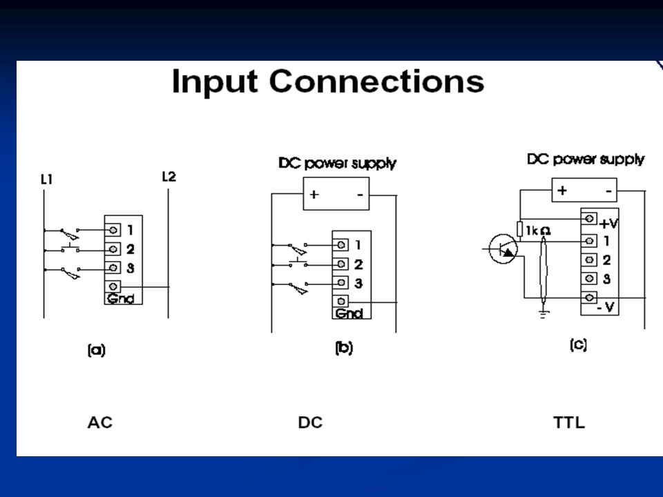
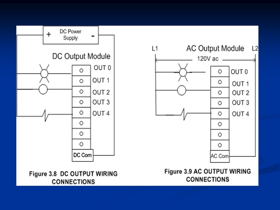
I/O Module The I/O interface section of a PLC connects it to external field devices. The main purpose of the I/O interface is to condition the various signals received from or sent to the external input and output devices. Input modules converts signals from discrete or analog input devices to logic levels acceptable to PLC’s processor. Output modules converts signal from the processor to levels capable of driving the connected discrete or analog output devices

20
I/O Module DC INPUT MODULE IS NEEDED TO:
OPTO- ISOLATOR IS NEEDED TO: Prevent voltage transients from damaging the processor. Helps reduce the effects of electrical noise Current Limiting Resistor FROM INPUT DEVICE USE TO DROP THE VOLTAGE TO LOGIC LEVEL Buffer, Filter, hysteresis Circuits TO PROCESSOR

21
I/O Module AC INPUT MODULE IS NEEDED TO:
OPTO- ISOLATOR IS NEEDED TO: Prevent voltage transients from damaging the processor. Helps reduce the effects of electrical noise Rectifier, Resistor Network FROM INPUT DEVICE CONVERTS THE AC INPUT TO DC AND DROPS THE VOLTAGE TO LOGIC LEVEL Buffer, Filter, Hysteresis Circuits TO PROCESSOR

22
Optocoupler 22

23
Optocoupler

25
I/O Module DC / AC OUTPUT MODULE IS NEEDED TO:
OPTO- ISOLATOR IS NEEDED TO: Prevent voltage transients from damaging the processor. Helps reduce the effects of electrical noise TTL Circuits Amplifier RELAY TRIAC X’SISTOR FROM PROCESSOR TO OUTPUT DEVICE

27
I/O Circuits DIFFERENT TYPES OF I/O CIRCUITS 1. Pilot Duty Outputs
Outputs of this type typically are used to drive high-current electromagnetic loads such as solenoids, relays, valves, and motor starters. These loads are highly inductive and exhibit a large inrush current. Pilot duty outputs should be capable of withstanding an inrush current of 10 times the rated load for a short period of time without failure.

28
I/O Circuits 2. General - Purpose Outputs
These are usually low- voltage and low-current and are used to drive indicating lights and other non-inductive loads. Noise suppression may or may not be included on this types of modules. 3. Discrete Inputs Circuits of this type are used to sense the status of limit switches, push buttons, and other discrete sensors. Noise suppression is of great importance in preventing false indication of inputs turning on or off because of noise.

29
I/O Circuits 4. Analog I/O
Circuits of this type sense or drive analog signals. Analog inputs come from devices, such as thermocouples, strain gages, or pressure sensors, that provide a signal voltage or current that is derived from the process variable. Standard Analog Input signals: 4-20mA; 0-10V Analog outputs can be used to drive devices such as voltmeters, X-Y recorders, servomotor drives, and valves through the use of transducers. Standard Analog Output signals: 4-20mA; 0-5V; 0-10V

30
I/O Circuits 5. Special - Purpose I/O
Circuits of this type are used to interface PLCs to very specific types of circuits such as servomotors, stepping motors PID (proportional plus integral plus derivative) loops, high-speed pulse counting, and decoder inputs, multiplexed displays, and keyboards. This module allows for limited access to timer and counter presets and other PLC variables without requiring a program loader.
 loops, high-speed pulse counting, and decoder inputs, multiplexed displays, and keyboards. This module allows for limited access to timer and counter presets and other PLC variables without requiring a program loader.")
34
OUTPUTS INPUTS MOTOR CONTACTOR LAMP PUSHBUTTONS PLC

35
O:4 LADDER PROGRAM L2 L1 L2 L1 FIELD WIRING OUTPUT MODULE WIRING L1 L2
CONTACTOR L2 L1 N.O MOTOR L2 SOLENOID VALVES LAMP BUZZER C L1 FIELD WIRING OUTPUT MODULE WIRING L1 O:4 L2 CONTACTOR LADDER PROGRAM

36
Discrete Input A discrete input also referred as digital input is an input that is either ON or OFF are connected to the PLC digital input. In the ON condition it is referred to as logic 1 or a logic high and in the OFF condition maybe referred to as logic o or logic low. Normally Open Pushbutton Normally Closed Pushbutton Normally Open switch Normally Closed switch Normally Open contact Normally closed contact

37
OFF PLC Logic 0 Input Module ON PLC Logic 1 Input Module IN 24 V dc IN
37

38
An analog input is an input signal that has a continuous
signal. Typical inputs may vary from 0 to 20mA, 4 to 20mA or 0 to10V. Below, a level transmitter monitors the level of liquid in the tank. Depending on the level Tx, the signal to the PLC can either increase or decrease as the level increases or decreases. Level Transmitter IN PLC Analog Input Module Tank

39
Digital Output A discrete output is either in an ON or OFF condition. Solenoids, contactors coils, lamps are example of devices connected to the Discrete or digital outputs. Below, the lamp can be turned ON or OFF by the PLC output it is connected to. OUT PLC Digital Output Module Lamp

40
An analog output is an output signal that has a continuous
signal. Typical outputs may vary from 0 to 20mA, 4 to 20mA or 0 to10V. Electric to pneumatic transducer OUT E Supply air PLC Analog Output Module 0 to 10V P Pneumatic control valve

41
Special I/O Thermocouple input
Low level analog signal, filtered, amplified, and digitized before sending to the processor through I/O bus. Fast input 50 to 100 microsecond pulse signal detection. ASCII I/O Communicates with ASCII devices. Stepper motor output Provide directly control of a stepper motor. Servo interface Control DC servo motor for point-to-point control and axis positioning. PID control The Proportional Integral Derivative is used for closed loop process control. Network module

42
Processor The processor module contains the PLC’s microprocessor, its supporting circuitry, and its memory system. The main function of the microprocessor is to analyze data coming from field sensors through input modules, make decisions based on the user’s defined control program and return signal back through output modules to the field devices. Field sensors: switches, flow, level, pressure, temp. transmitters, etc. Field output devices: motors, valves, solenoids, lamps, or audible devices. The memory system in the processor module has two parts: a system memory and an application memory.

43
Memory Map Organization
System memory includes an area called the EXECUTIVE, composed of permanently-stored programs that direct all system activities, such as execution of the users control program, communication with peripheral devices, and other system activities. The system memory also contains the routines that implement the PLC’s instruction set, which is composed of specific control functions such as logic, sequencing, timing, counting, and arithmetic. System memory is generally built from read-only memory devices. SYSTEM APPLICATION The application memory is divided into the data table area and user program area. The data table stores any data associated with the user’s control program, such as system input and output status data, and any stored constants, variables, or preset values. The data table is where data is monitored, manipulated, and changed for control purposes. The user program area is where the programmed instructions entered by the user are stored as an application control program. Data Table User Program

44
While the PLC is running, the scanning process includes the following four phases, which are repeated continuously as individual cycles of operation: PHASE 1 Read Inputs Scan PHASE 2 Program Execution PHASE 3 Diagnostics/ Comm PHASE 4 Output Scan

45
PHASE 1 – Input Status scan
A PLC scan cycle begins with the CPU reading the status of its inputs. PHASE 2– Logic Solve/Program Execution The application program is executed using the status of the inputs PHASE 3– Diagnostics/Comm Once the program is executed, the CPU performs diagnostics and communication tasks 45

46
PHASE 4 - Output Status Scan
An output status scan is then performed, whereby the stored output values are sent to actuators and other field output devices. The cycle ends by updating the outputs.

47
As soon as Phase 4 are completed, the entire cycle begins again with Phase 1 input scan.
The time it takes to implement a scan cycle is called SCAN TIME. The scan time composed of the program scan time, which is the time required for solving the control program, and the I/O update time, or time required to read inputs and update outputs. The program scan time generally depends on the amount of memory taken by the control program and type of instructions used in the program. The time to make a single scan can vary from 1 ms to 100 ms.

48
PLC Communications Common Uses of PLC Communications Ports
Changing resident PLC programs - uploading/downloading from a supervisory controller (Laptop or desktop computer). Forcing I/O points and memory elements from a remote terminal. Linking a PLC into a control hierarchy containing several sizes of PLC and computer. Monitoring data and alarms, etc. via printers or Operator Interface Units (OIUs).
. Forcing I/O points and memory elements from a remote terminal. Linking a PLC into a control hierarchy containing several sizes of PLC and computer. Monitoring data and alarms, etc. via printers or Operator Interface Units (OIUs).")
49
Serial Communications
PLC communications facilities normally provides serial transmission of information. RS Used in short-distance computer communications, with the majority of computer hardware and peripherals. Has a maximum effective distance of approx. 30 m at 9600 baud.

50
PLC Communications RS 422 / RS 485
Used for longer-distance links, often between several PCs in a distributed system. RS 485 can have a maximum distance of about 1000 meters.

51
PLC Communications Local Area Network (LAN)
Local Area Network provides a physical link between all devices plus providing overall data exchange management or protocol, ensuring that each device can “talk” to other machines and understand data received from them. LANs provide the common, high-speed data communications bus which interconnects any or all devices within the local area. LANs are commonly used in business applications to allow several users to share costly software packages and peripheral equipment such as printers and hard disk storage.

52
PLC Communications Programmable Controllers and Networks
Dedicated Network System of Different Manufacturers 52

53
Specifications Several factors are used for evaluating the quality and performance of programmable controllers when selecting a unit for a particular application. These are listed below.

54
Specifications NUMBER OF I /O PORTS
This specifies the number of I/O devices that can be connected to the controller. There should be sufficient I/O ports to meet present requirements with enough spares to provide for moderate future expansion.

Similar presentations

>")


 4/19/2017 A digitally operating electronic apparatus which uses a programming.>")


