Download presentation
Presentation is loading. Please wait.

1
ECE 476 Power System Analysis Lecture 6: Power System Operations, Transmission Line Parameters Prof. Tom Overbye Dept. of Electrical and Computer Engineering University of Illinois at Urbana-Champaign overbye@illinois.edu

2
Announcements Please read Chapter 4 Quiz today on HW 2 HW 3 is 4.8, 4.10, 4.18, 4.23 It does not need to be turned in, but will be covered by an in-class quiz on Sept 17 Positive sequence is same as per phase; it will be covered in Chapter 8 Use Table A.4 values to determine the Geometric Mean Radius of the wires (i.e., the ninth column).
.")
3
Generator Costs There are many fixed and variable costs associated with power system operation. The major variable cost is associated with generation. Cost to generate a MWh can vary widely. For some types of units (such as hydro and nuclear) it is difficult to quantify. For thermal units it is much easier. These costs will be discussed later in the course. 2
 it is difficult to quantify. For thermal units it is much easier. These costs will be discussed later in the course. 2.")
4
Economic Dispatch Economic dispatch (ED) determines the least cost dispatch of generation for an area. For a lossless system, the ED occurs when all the generators have equal marginal costs. IC 1 (P G,1 ) = IC 2 (P G,2 ) = … = IC m (P G,m ) 3
 = IC 2 (P G,2 ) = … = IC m (P G,m ) 3.")
5
Power Transactions Power transactions are contracts between areas to do power transactions. Contracts can be for any amount of time at any price for any amount of power. Scheduled power transactions are implemented by modifying the area ACE: ACE = P actual,tie-flow - P sched 4

6
100 MW Transaction Scheduled 100 MW Transaction from Left to Right Net tie-line flow is now 100 MW 5

7
Security Constrained ED Transmission constraints often limit system economics. Such limits required a constrained dispatch in order to maintain system security. In three bus case the generation at bus 3 must be constrained to avoid overloading the line from bus 2 to bus 3. 6

8
Security Constrained Dispatch Dispatch is no longer optimal due to need to keep line from bus 2 to bus 3 from overloading 7

9
Multi-Area Operation If Areas have direct interconnections, then they may directly transact up to the capacity of their tie- lines. Actual power flows through the entire network according to the impedance of the transmission lines. Flow through other areas is known as “parallel path” or “loop flows.” 8

10
Seven Bus Case: One-line System has three areas Area left has one busArea right has one bus Area top has five buses 9

11
Seven Bus Case: Area View System has 40 MW of “Loop Flow” Actual flow between areas Loop flow can result in higher losses Scheduled flow 10

12
Seven Bus - Loop Flow? 100 MW Transaction between Left and Right Transaction has actually decreased the loop flow Note that Top’s Losses have increased from 7.09MW to 9.44 MW 11

13
Pricing Electricity Cost to supply electricity to bus is called the locational marginal price (LMP) Presently some electric makets post LMPs on the web In an ideal electricity market with no transmission limitations the LMPs are equal Transmission constraints can segment a market, resulting in differing LMP Determination of LMPs requires the solution on an Optimal Power Flow (OPF) 12
 Presently some electric makets post LMPs on the web In an ideal electricity market with no transmission limitations the LMPs are equal Transmission constraints can segment a market, resulting in differing LMP Determination of LMPs requires the solution on an Optimal Power Flow (OPF) 12")
14
3 BUS LMPS - OVERLOAD IGNORED Line from Bus 1 to Bus 3 is over-loaded; all buses have same marginal cost Gen 1’s cost is $10 per MWh Gen 2’s cost is $12 per MWh 13

15
LINE OVERLOAD ENFORCED Line from 1 to 3 is no longer overloaded, but now the marginal cost of electricity at 3 is $14 / MWh 14

16
MISO LMPs 9/5/15 at 8:45 AM https://www.misoenergy.org/LMPContourMap/MISO_All.html

17
Development of Line Models Goals of this section are 1)develop a simple model for transmission lines 2)gain an intuitive feel for how the geometry of the transmission line affects the model parameters
develop a simple model for transmission lines 2)gain an intuitive feel for how the geometry of the transmission line affects the model parameters")
18
Primary Methods for Power Transfer The most common methods for transfer of electric power are – Overhead ac – Underground ac – Overhead dc – Underground dc – other

19
18 345 kV+ Transmission Growth at a Glance

20
19 345 kV+ Transmission Growth at a Glance

21
20 345 kV+ Transmission Growth at a Glance

22
21 345 kV+ Transmission Growth at a Glance

23
22 345 kV+ Transmission Growth at a Glance

24
Grid Weakness

25
Ameren Illinois Rivers 345 kV Project Ameren is in the process of building a number of 345 kV transmission lines across Central Illinois. Locally this includes a line between Sidney and Rising in Champaign County http://www.ilriverstransmission.com/maps

26
Sidney to Bunsonville 345 kV

27
Sidney to Kansas (IL) 345
 345")
28
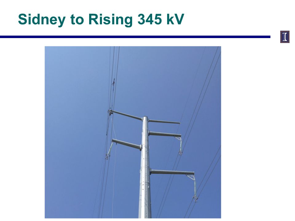
Sidney to Rising 345 kV

30
Champaign-Urbana Part of Grid

31
Line Conductors Typical transmission lines use multi-strand conductors ACSR (aluminum conductor steel reinforced) conductors are most common. A typical Al. to St. ratio is about 4 to 1.

Similar presentations

. HW 5 is 2.38, 6.9, 6.18, 6.30, 6.34, 6.38; do by October 6 but does not need.>")


