Download presentation
Presentation is loading. Please wait.

2
HF Com Chapter 4 High Frequency Communications

5
Textbook page 23 When an airplane leaves the coastline for a transoceanic flight, it moves into a polar region or ventures over a remote area, it loses VHF communications. VHF signals are line of sight and cannot curve over the horizon. For long-range flight, the airplane switches to HF (High frequency) communications. Textbook page 23
 communications. Textbook page 23.")
6
Radio Frequency (RF ) Very Low Frequency VLF 3 kHz -30 kHz Low Frequency LF 30 kHz - 300 kHz Medium Frequency MF 300 kHz - 3 MHz High Frequency HF 3 MHz - 30 MHz Very High Frequency VHF 30 MHz - 300 MHz Ultra High Frequency UHF 300 MHz - 3 GHz Super High FrequencySHF 3 GHz - 30 GHz Extremely High Frequency EHF 30 GHz -300 GHz HF isn’t very High
 Very Low Frequency VLF 3 kHz -30 kHz Low Frequency LF 30 kHz kHz Medium Frequency MF 300 kHz - 3 MHz High Frequency HF 3 MHz - 30 MHz Very High Frequency VHF 30 MHz MHz Ultra High Frequency UHF 300 MHz - 3 GHz Super High FrequencySHF 3 GHz - 30 GHz Extremely High Frequency EHF 30 GHz -300 GHz HF isn’t very High")
7
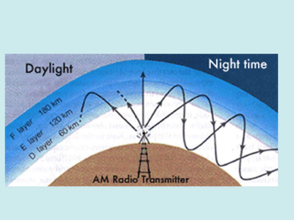
HF Com Works by “skipping” through the ionosphere. Since the ionosphere is not constant, and changes between day and night and season to season, HF isn’t always reliable. Will eventually be replaced by satellite communications (SAT COM).
..")
9
Antenna Tuning via Antenna Coupler Uses ¼ wave antenna. However with varying frequencies this could be impractical as the lower frequencies could require an antenna > 100 feet long. The Autotune system eliminates the need for long antennas by using tuning circuits in the antenna coupler to electrically match up, thus enabling the use of a short-fixed length antenna. Textbook page 24 “Coupler”

10
HF System Textbook page 24

11
Single Sideband (SSB) HF radio transmits using AM (amplitude modulation). AM has 3 components: The RF carrier, and an upper (USB) and lower (LSB) sideband. Originally, most of the power was lost in the carrier in AM. Since voice audio only uses the sidebands, modern transmitters direct the transmitter power into one sideband thus not losing it in the carrier signal. Textbook page 25
 and lower (LSB) sideband. Originally, most of the power was lost in the carrier in AM. Since voice audio only uses the sidebands, modern transmitters direct the transmitter power into one sideband thus not losing it in the carrier signal. Textbook page 25.")
12
Modulation Signal Information Carrier Wave Modulated Carrier Wave

14
HF System Page 27 Page 26 Page 25

15
Review Q&A Chapter 4 HF Com 4.1 Why are High Frequency communications not as reliable as VHF? Answer: Because HF depends on varying atmospheric conditions to work. 4.2 What is the advantage of “Autotune”? Answer: It allows for a short-fixed antenna and eliminates the need for the pilot to tune the radio. 4.3 Why is SSB (single sideband) more efficient than conventional AM radio? Answer: It directs the transmitter power to the sideband thus eliminating losses in the carrier signal. 4.4 What made HF datalink possible? Answer: Improved filtering technology. 4.5 What are 3 major components of an HF LRU? Answer: Antenna Coupler, Power Amplifier, and Receiver-Exciter.
 more efficient than conventional AM radio. Answer: It directs the transmitter power to the sideband thus eliminating losses in the carrier signal. 4.4 What made HF datalink possible. Answer: Improved filtering technology. 4.5 What are 3 major components of an HF LRU. Answer: Antenna Coupler, Power Amplifier, and Receiver-Exciter..")
16
Review Q&A Chapter 4 HF Com 4.5 What are 3 major components of an HF LRU? Answer: Antenna Coupler, Power Amplifier, and Receiver-Exciter 4.6 Name 2 advantages of HF datalink. Answer: Lower pilot workload, Shorter Message Transmission time, Lower channel access time, Less Training for flight crew, Relieves congestion on voice frequencies, Automatic selection of frequency & data rates, Less vulnerability to human error, Automatically detects and corrects errors, can operate in noisier environments, Increases HF traffic capability, assured communications link, automatic air/ground HF linkage with lower acquisition cost compared to SATCOM, improved voice/data quality and datalink messages are not written or sensitive to verbal language. 4.7 What is the purpose of an HF antenna coupler? Answer: To tune the antenna 4.8 Where is the HF antenna mounted on many airliners? Answer: In the vertical stabilizer.

17
SatCom Chapter 5 Satellite Communications

18
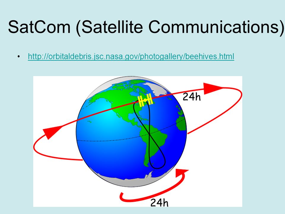
Textbook page 34 AES (Aircraft Earth Station) Satellite GES (Ground Earth Station) SatCom (Satellite Communications)
 Satellite GES (Ground Earth Station) SatCom (Satellite Communications)")
19
http://orbitaldebris.jsc.nasa.gov/photogallery/beehives.html
20
http://www.duncanaviation.aero/homepage.php http://www.duncanaviation.aero/straighttalk/index.php
21
Antenna Mounting HF and Satcom HF page 27 Satcom page 37

22
VHF Comm Antennas

23
Aircraft Structures

24
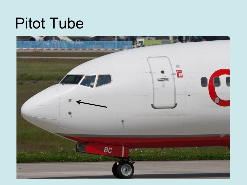
Pitot-Static System Some of the most important flight instruments derive their indications from measuring air pressure. Gathering and distributing various air pressures for flight instrumentation is the function of the pitot-static system. FAA H 8083-31 Vol 2 Page 10-12

25
Pitot Tube

28
Static Port

29
AOA Sensor

30
Pitot-Static System Airspeed Vertical Speed Indicator Altimeter

31
6 Pack or Basic “T” Textbook page 157

32
ASI Air Speed Indicator Pitot Static System

33
Altimeter

34
VSI Vertical Speed Indicator

35
Turn Coordinator

36
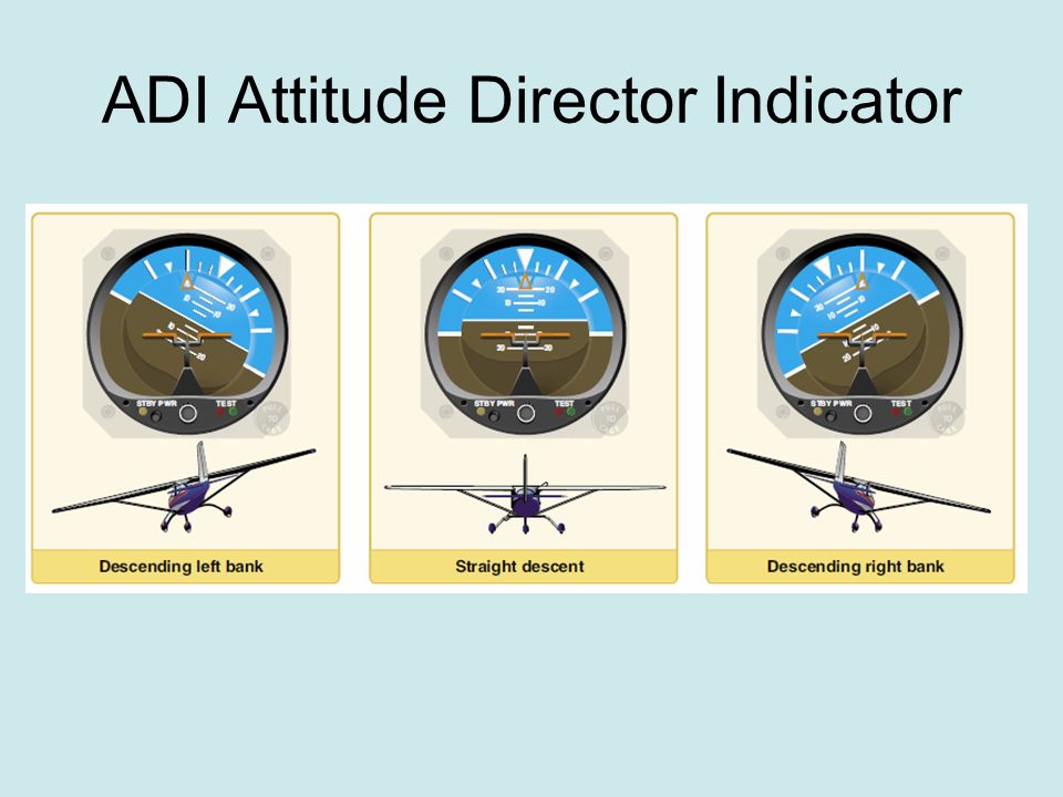
ADI Attitude Director Indicator

40
6 Pack or Basic “T” Textbook page 157

Similar presentations


 Radio ??. It’s a hobby, a technical hobby with a large number of different activities within it. It contains a certain element.>")


>")


 ©2003 Glencoe/McGraw-Hill Charles A. Schuler.>")


 waves to transfer information –TV, mobile.>")
 Radio Communications>")