Download presentation
Presentation is loading. Please wait.

1
I. Analytical Developments Cryogenic-Free Focusing System Cryogenic-Free Chromatography System gas-free Gas Chromatography Low Power Needs Portable – Modular Instrument Low pptv Detection Limits Detlev Helmig II. Continuous Free Tropospheric Monitoring of NMHC at Pico Mountain, Azores, Portugal III. Global NMHC Monitoring at 25 NOAA Greenhouse Gas Monitoring Network Sites Continuous and Global NMHC Monitoring Research

2
Contributions Jacques Hueber John Ortega Jan Pollmann David Tanner Pieter Tans

3
Adsorbent materials with their properties: Density: gravimetric density; Surface Area: Surface Area as provided by supplier; net adsorbent mass: mass of individual adsorbent filled into trap for evaluation; Pressure Drop: pressure drop across adsorbent trap filled with adsorbent.

4
Recovery for target compounds from Carbosieve S III at –10 and –30 ºC. Dark gray section represents the peak area that was found on the microtrap for the respective peak after the first injection, indicating desorption efficiency. Error bars indicate standard deviation for n = 5 injections.

5
Recovery for target compounds from 3-stage adsorbent microtrap (Carboxen 1016, Carboxen 563, Carbosieve S III) at –30 ºC. Dark gray section represents the peak area that was found on the microtrap for the respective peak after the first injection, indicating desorption efficiency. Error bars indicate standard deviation for n = 15 injections.

6
Adsorbent trap schematic. All dimensions are given in millimeters. Figure is not to scale, radial axis is exaggerated. EC = Electrical Connector, RT = Retaining Tube, TC = Thermocouple. RT I.D. = 1.02 mm, trap tube I.D. = 1.83 mm, and trap tube O.D. = 2.11 mm.

7
Adsorbent trap assembly schematic. Bottom cover has been moved and front cover has been removed to show detail inside the assembly housing.

8
Photo: Rick Wunderman, 1997 (Smithsonian Institution www.si.edu) II. Pico-NARE site

9
Measurements at Pico: July 2001 – present: CO, O3, Black Carbon, Meteorology Aug 2002 – present: NO, NO2, NOy July 2004 – present: Non-Methane Hydrocarbons

10
Pico-NARE Atmospheric Observatory

11
Portability / Modular / Size Limited power Cryogen free No consumable gasses Remote control Unattended operation for long periods Low free troposphere background concentrations NMHC Monitoring Challenges

13
Pico-GC Calibration Runs

14
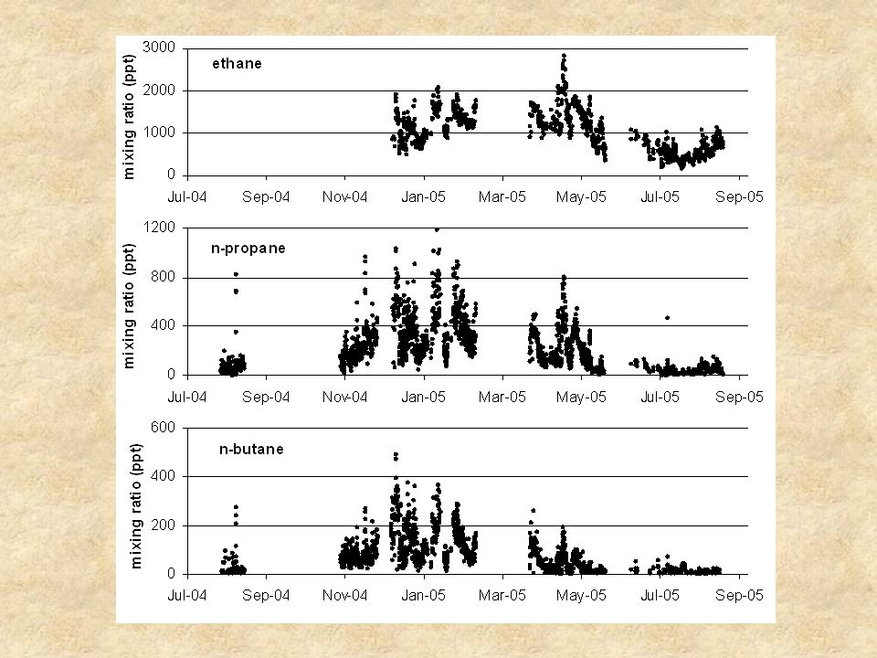
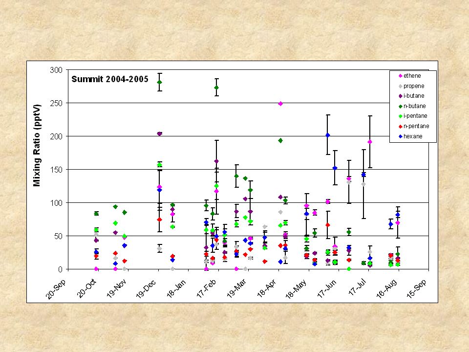
NMHC Results from Pico-NARE

15
NMHC ratios from Pico-NARE

16
NMHC ratios and transport time at the Pico-NARE site

17
III. Global Network NMHC Monitoring

18
Search GMD:

19
NMHC-Flask Instrument

20
NMHC Stations and Available Data

25
Ambient & Blank Chromatograms 600 mL 3000 mL

26
Reference Standard Chromatograms Cryogenic system Pico system

28
Compound R.F. (PA/vol)/ppbR.F. (%) RSD D.L. (ppt) 600 mL sample D.L. (ppt) 3000 mL sample Ethane0.0367560 Propane0.0590515631 Propene0.067255311 i-Butane0.072556.91.4 n-Butane0.063457.91.6 1-Butene0.0530109.41.9 i-Pentane0.061968.11.6 n-Pentane0.056068.91.8 Pico GC NMHC Detection Limits
 3000 mL sample Ethane Propane Propene i-Butane n-Butane Butene i-Pentane n-Pentane Pico GC NMHC Detection Limits.")
29
Schematic of the trapping and GC system with components for sample collection. V1 = 4-Port Valco Valve, V2 = 4-Port Valco Valve, V3 = 6-Port Valco Valve, SO1 through SO5 = KIP solenoid shut-off valves, P1 through P6 = Medo compressors and vacuum pumps, MFC1 through 3 = Mass Flow Controllers, GC = Gas Chromatograph, FID = Flame Ionization Detector, Al/KCl PLOT = Al/KCl PLOT column, Cat = Zero Air Catalyst, Vol = 1 L buffer volume, R1 = 5 L min-1 rotometer, R2 and R3 = 0.5 L min-1 rotometer, Std 1 and 2 = Reference Standards 1 and 2, NV = Needle Valve, Blank = Blank Air Flow, Dry Purge = Water Trap Dry Purge Flow, H2O Trap = Water Trap, O3 Trap = Ozone Trap, Ads Trap = Adsorbent Focusing Trap, Pres Sens = Pressure Sensor, H2 Gen = Hydrogen Generator, Scrub = Hydrocarbon Scrubber, Oxygen Scrubber, and Indicating Oxygen Scrubber. Tubing that is connected to the adsorbent trap while it is in the isolated mode has been highlighted.

30
Temperature gradient in the adsorbent trap during heating as a function of the distance from the center of the trap. EC = Electrical Connector.

31
Temperature of the adsorbent trap as a function of time with the flash heat (12 s), inject (12 s) and bakeout (60 s) periods labeled.
, inject (12 s) and bakeout (60 s) periods labeled.")
33
Analyte recovery as a function of increasing desorption temperature.

34
Peak areas resulting from increasing sampling volumes of the breathing air standard.

Similar presentations