Download presentation
Presentation is loading. Please wait.

1
Integrated Services Digital Network

2
Introduction Integrated Services Digital Network (ISDN) is comprised of digital telephony and data-transport services offered by regional telephone carriers. ISDN involves the digitization of the telephone network, which permits voice, data, text, graphics, music, video, and other source material to be transmitted over existing telephone wires. The emergence of ISDN represents an effort to standardize subscriber services, user/network interfaces, and network and internetwork capabilities. ISDN applications include high-speed image applications (such as Group IV facsimile), additional telephone lines in homes to serve the telecommuting industry, high-speed file transfer, and videoconferencing. Voice service is also an application for ISDN.
 is comprised of digital telephony and data-transport services offered by regional telephone carriers. ISDN involves the digitization of the telephone network, which permits voice, data, text, graphics, music, video, and other source material to be transmitted over existing telephone wires. The emergence of ISDN represents an effort to standardize subscriber services, user/network interfaces, and network and internetwork capabilities. ISDN applications include high-speed image applications (such as Group IV facsimile), additional telephone lines in homes to serve the telecommuting industry, high-speed file transfer, and videoconferencing. Voice service is also an application for ISDN.")
3
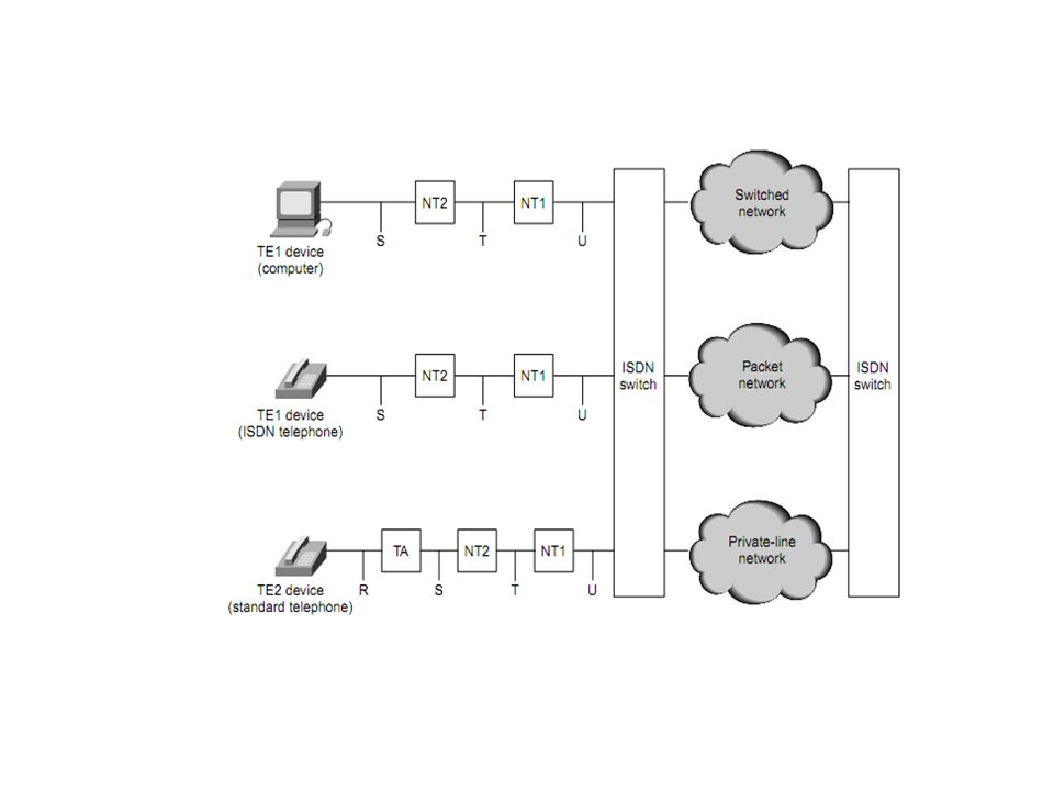
ISDN Devices ISDN devices include terminals, terminal adapters (TAs), network-termination devices, line-termination equipment, and exchange-termination equipment. ISDN terminals come in two types. Specialized ISDN terminals are referred to as terminal equipment type 1 (TE1). Non-ISDN terminals, such as DTE, that predate the ISDN standards are referred to as terminal equipment type 2 (TE2). TE1s connect to the ISDN network through a four-wire, twisted-pair digital link. TE2s connect to the ISDN network through a TA. The ISDN TA can be either a standalone device or a board inside the TE2. If the TE2 is implemented as a standalone device, it connects to the TA via a standard physical-layer interface. Examples include EIA/TIA-232-C (formerly RS-232-C), V.24, and V.35
, network-termination devices, line-termination equipment, and exchange-termination equipment. ISDN terminals come in two types. Specialized ISDN terminals are referred to as terminal equipment type 1 (TE1). Non-ISDN terminals, such as DTE, that predate the ISDN standards are referred to as terminal equipment type 2 (TE2). TE1s connect to the ISDN network through a four-wire, twisted-pair digital link. TE2s connect to the ISDN network through a TA. The ISDN TA can be either a standalone device or a board inside the TE2. If the TE2 is implemented as a standalone device, it connects to the TA via a standard physical-layer interface. Examples include EIA/TIA-232-C (formerly RS-232-C), V.24, and V.35.")
4
Beyond the TE1 and TE2 devices, the next connection point in the ISDN network is the network termination type 1 (NT1) or network termination type 2 (NT2) device. These are network-termination devices that connect the four-wire subscriber wiring to the conventional two-wire local loop. The NT2 is a more complicated device that typically is found in digital private branch exchanges (PBXs) and that performs Layer 2 and 3 protocol functions and concentration services. An NT1/2 device also exists as a single device that combines the functions of an NT1 and an NT2
 and that performs Layer 2 and 3 protocol functions and concentration services. An NT1/2 device also exists as a single device that combines the functions of an NT1 and an NT2.")
5
ISDN reference points include the following:
ISDN specifies a number of reference points that define logical interfaces between functional groups, such as TAs and NT1s. ISDN reference points include the following: R: The reference point between non-ISDN equipment and a TA. S: The reference point between user terminals and the NT2. T: The reference point between NT1 and NT2 devices. U: The reference point between NT1 devices and line-termination equipment in the carrier network. The U reference point is relevant only in North America, where the NT1 function is not provided by the carrier network.

7
Services There are two types of services associated with ISDN:
Basic Rate Interface (BRI) The ISDN Basic Rate Interface (BRI) service offers two B channels and one D channel (2B+D). BRI B-channel service operates at 64 kbps and is meant to carry user data; BRI D-channel service operates at 16 kbps and is meant to carry control and signaling information, although it can support user data transmission under certain circumstances. The D channel signaling protocol comprises Layers 1 through 3 of the OSI reference model. BRI also provides for framing control and other overhead, bringing its total bit rate to 192 kbps.
 The ISDN Basic Rate Interface (BRI) service offers two B channels and one D channel (2B+D). BRI B-channel service operates at 64 kbps and is meant to carry user data; BRI D-channel service operates at 16 kbps and is meant to carry control and signaling information, although it can support user data transmission under certain circumstances. The D channel signaling protocol comprises Layers 1 through 3 of the OSI reference model. BRI also provides for framing control and other overhead, bringing its total bit rate to 192 kbps.")
8
ISDN Primary Rate Interface (PRI)
service offers 23 B channels and 1 D channel in North America and Japan, yielding a total bit rate of Mbps (the PRI D channel runs at 64 kbps). ISDN PRI in Europe, Australia, and other parts of the world provides 30 B channels plus one 64-kbps D channel and a total interface rate of Mbps.
. ISDN PRI in Europe, Australia, and other parts of the world provides 30 B channels plus one 64-kbps D channel and a total interface rate of Mbps.")
9
ISDN Specifications Layer 1
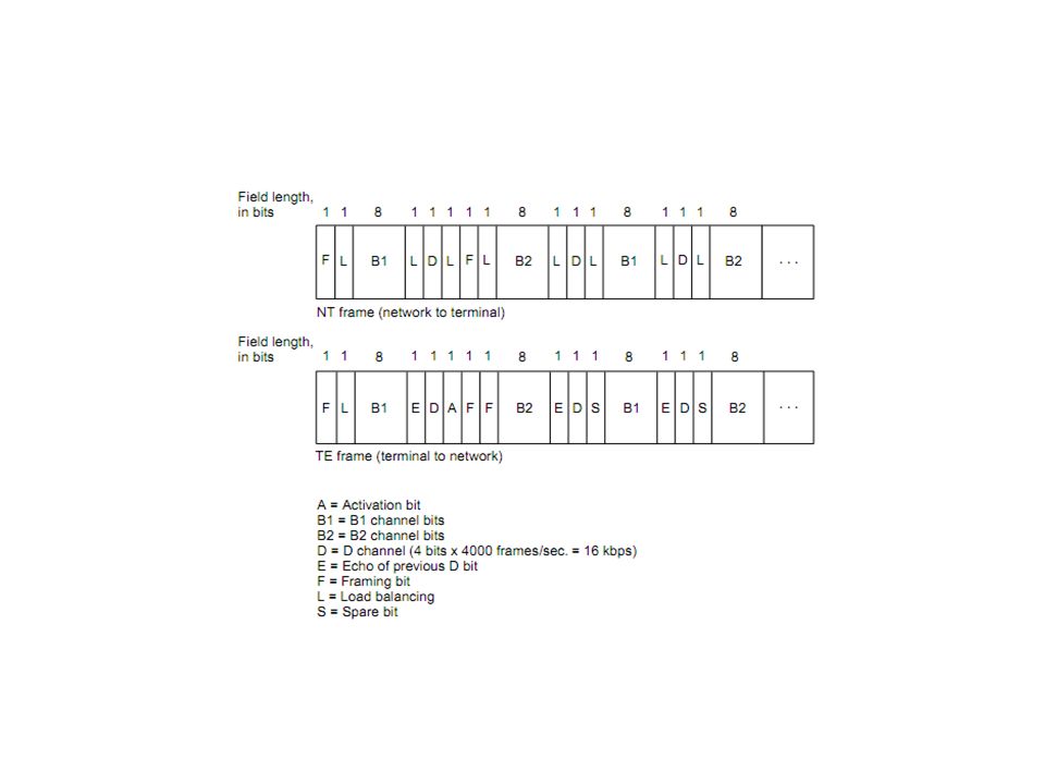
ISDN physical layer (Layer 1) frame formats differ depending on whether the frame is outbound (from terminal to network) or inbound (from network to terminal). The frames are 48 bits long, of which 36 bits represent data. The bits of an ISDN physical layer frame are used as follows: F: Provides synchronization L: Adjusts the average bit value E: Ensures contention resolution when several terminals on a passive bus contend for a channel A: Activates devices S: Is unassigned B1, B2, and D: Handle user data
 frame formats differ depending on whether the frame is outbound (from terminal to network) or inbound (from network to terminal). The frames are 48 bits long, of which 36 bits represent data. The bits of an ISDN physical layer frame are used as follows: F: Provides synchronization. L: Adjusts the average bit value. E: Ensures contention resolution when several terminals on a passive bus contend for a channel. A: Activates devices. S: Is unassigned. B1, B2, and D: Handle user data.")
11
Multiple ISDN user devices can be physically attached to one circuit.
In this configuration, collisions can result if two terminals transmit simultaneously. Therefore, ISDN provides features to determine link contention. When an NT receives a D bit from the TE, it echoes back the bit in the next E-bit position. The TE expects the next E bit to be the same as its last transmitted D bit.

12
Terminals cannot transmit into the D channel unless they first detect a specific number of ones (indicating “no signal”) corresponding to a pre-established priority. If the TE detects a bit in the echo (E) channel that is different from its D bits, it must stop transmitting immediately. This simple technique ensures that only one terminal can transmit its D message at one time. After successful D-message transmission, the terminal has its priority reduced by requiring it to detect more continuous ones before transmitting. Terminals cannot raise their priority until all other devices on the same line have had an opportunity to send a D message. Telephone connections have higher priority than all other services, and signaling information has a higher priority than non signaling information.
 channel that is different from its D bits, it must stop transmitting immediately. This simple technique ensures that only one terminal can transmit its D message at one time. After successful D-message transmission, the terminal has its priority reduced by requiring it to detect more continuous ones before transmitting. Terminals cannot raise their priority until all other devices on the same line have had an opportunity to send a D message. Telephone connections have higher priority than all other services, and. signaling information has a higher priority than non signaling information.")
13
Layer 2 Layer 2 of the ISDN signaling protocol is Link Access Procedure, D channel (LAPD). LAPD is similar to High-Level Data Link Control (HDLC) and Link Access Procedure, Balanced (LAPB) As the expansion of the LAPD acronym indicates, this layer is used across the D channel to ensure that control and signaling information flows and is received properly. The LAPD frame format is very similar to that of HDLC; like HDLC, LAPD uses supervisory, information, and unnumbered frames. The LAPD protocol is formally specified in ITU-T Q.920 and ITU-T Q.921
 and Link Access Procedure, Balanced (LAPB) As the expansion of the LAPD acronym indicates, this layer is used across the D channel to ensure that control and signaling information flows and is received properly. The LAPD frame format is very similar to that of HDLC; like HDLC, LAPD uses supervisory, information, and unnumbered frames. The LAPD protocol is formally specified in ITU-T Q.920 and ITU-T Q.921.")
15
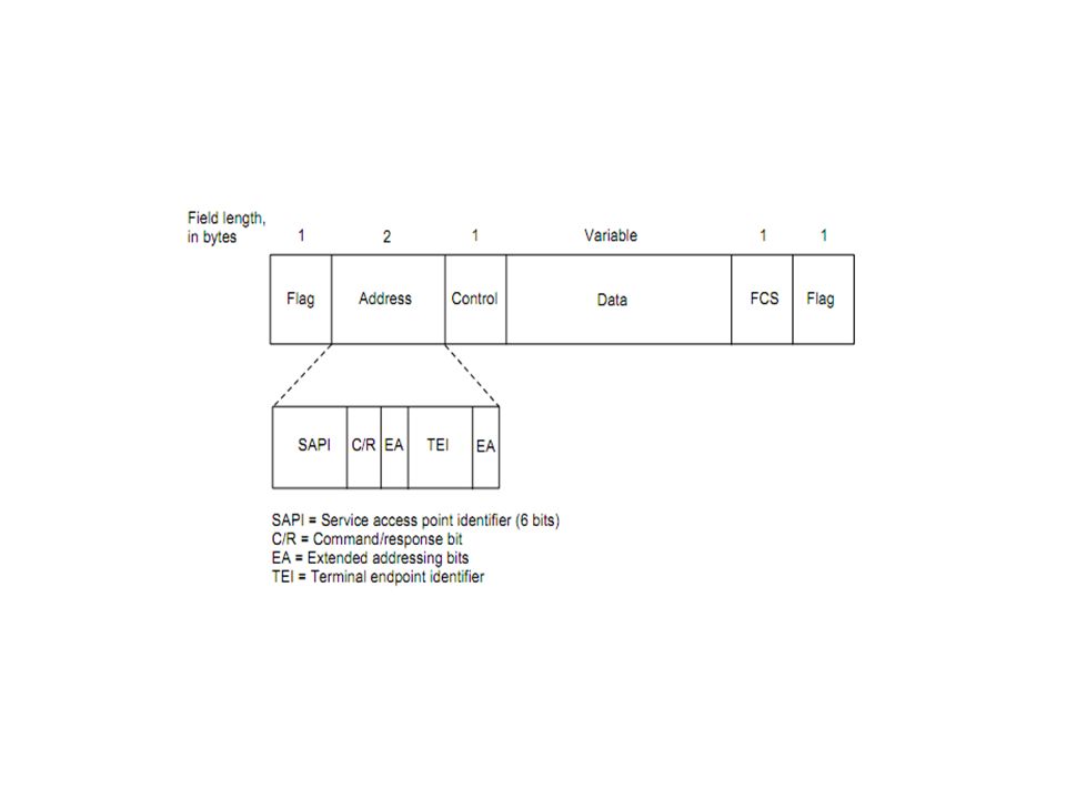
The LAPD Flag and Control fields are identical to those of HDLC.
The LAPD Address field can be either 1 or 2 bytes long. If the extended address bit of the first byte is set, the address is 1 byte; if it is not set, the address is 2 bytes. The first Address-field byte contains the service access point identifier (SAPI), which identifies the portal at which LAPD services are provided to Layer 3. The C/R bit indicates whether the frame contains a command or a response. The Terminal Endpoint Identifier (TEI) field identifies either a single terminal or multiple terminals. A TEI of all ones indicates a broadcast.
, which identifies the portal at which LAPD services are provided to Layer 3. The C/R bit indicates whether the frame contains a command or a response. The Terminal Endpoint Identifier (TEI) field identifies either a single terminal or multiple terminals. A TEI of all ones indicates a broadcast.")
16
Layer 3 Two Layer 3 specifications are used for ISDN signaling: ITU-T (formerly CCITT) I.450 (also known as ITU-T Q.930) and ITU-T I.451 (also known as ITU-T Q.931). Together, these protocols support user-to-user, circuit-switched, and packet-switched connections. A variety of call-establishment, call-termination, information, and miscellaneous messages are specified, including SETUP, CONNECT, RELEASE, USER INFORMATION, CANCEL, STATUS, and DISCONNECT. These messages are functionally similar to those provided by the X.25 protocol
 I.450 (also known as ITU-T Q.930) and ITU-T I.451 (also known as ITU-T Q.931). Together, these protocols support user-to-user, circuit-switched, and packet-switched connections. A variety of call-establishment, call-termination, information, and miscellaneous messages are specified, including SETUP, CONNECT, RELEASE, USER INFORMATION, CANCEL, STATUS, and DISCONNECT. These messages are functionally similar to those provided by the X.25 protocol.")
Similar presentations

 CT 1401>")
>")


 HDLC was defined by ISO for use on both point-to-point and multipoint data links. It supports full-duplex communication.>")


 Monash University>")


 is comprised of digital telephony and data-transport services offered by.>")


