Download presentation
Presentation is loading. Please wait.

1
CACHE MEMORY Cache memory, also called CPU memory, is random access memory (RAM) that a computer microprocessor can access more quickly than it can access regular RAM. This memory is typically integrated directly with the CPU chip or placed on a separate chip that has a separate bus interconnect with the CPU.

2
CACHE MEMORY

3
The basic purpose of cache memory is to store program instructions that are frequently re- referenced by software during operation. Fast access to these instructions increases the overall speed of the software program. As the microprocessor processes data, it looks first in the cache memory; if it finds the instructions there (from a previous reading of data), it does not have to do a more time- consuming reading of data from larger memory or other data storage devices.
, it does not have to do a more time- consuming reading of data from larger memory or other data storage devices..")
4
Key Characteristics of Computer Memory Systems

5
The term location refers to whether memory is internal and external to the computer. Internal memory is often equated with main memory. The processor requires its own local memory, in the form of registers. External memory consists of peripheral storage devices, such as disk and tape, that are accessible to the processor via I/O controllers.

6
Key Characteristics of Computer Memory Systems An obvious characteristic of memory is its capacity. For internal memory, this is typically expressed in terms of bytes (1 byte 8 bits) or words. Common word lengths are 8, 16, and 32 bits.
 or words. Common word lengths are 8, 16, and 32 bits..")
7
Key Characteristics of Computer Memory Systems For internal memory, the unit of transfer is equal to the number of electrical lines into and out of the memory module. This may be equal to the word length, but is often larger, such as 64, 128, or 256 bits.

8
Key Characteristics of Computer Memory Systems Method of accessing include the following: Sequential access: Memory is organized into units of data, called records. Access must be made in a specific linear sequence. Tape units are sequential access. Direct access: individual blocks or records have a unique address based on physical location. Access is accomplished by direct access to reach a general vicinity plus sequential searching, counting, or waiting to reach the final location. Disk units are direct access.

9
Key Characteristics of Computer Memory Systems Method of accessing include the following: Random access: Each addressable location in memory has a unique, physically wired-in addressing mechanism. The time to access a given location is independent of the sequence of prior accesses and is constant. Thus, any location can be selected at random and directly addressed and accessed. Main memory and some cache systems are random access. Associative: This is a random access type of memory that enables one to make a comparison of desired bit locations within a word for a specified match, and to do this for all words simultaneously. Cache memories may employ associative access.

10
Key Characteristics of Computer Memory Systems Three performance parameters are used: Access time (latency): For random-access memory, this is the time it takes to perform a read or write operation. For non-random-access memory, access time is the time it takes to position the read–write mechanism at the desired location. Memory cycle time: This consists of the access time plus any additional time required before a second access can commence. Transfer rate: This is the rate at which data can be transferred into or out of a memory unit.

11
Key Characteristics of Computer Memory Systems Physical types of memory are semiconductor memory, magnetic memory, used for disk and tape, and optical and magneto-optical. The organization is a key design issue. Organization meant the physical arrangement of bits to form words.

12
Key Characteristics of Computer Memory Systems Physical characteristics of data storage are important. In a volatile memory, information decays naturally or is lost when electrical power is switched off. In a nonvolatile memory, information once recorded remains without deterioration until deliberately changed. Non erasable memory cannot be altered, except by destroying the storage unit.

13
Transfer rate For random-access memory, it is equal to 1/(cycle time). For non-random-access memory, the following relationship holds:

14
Average access time Suppose that the processor has access to two levels of memory. Level 1 contains 1000 words and has an access time of 0.01 µs; level 2 contains 100,000 words and has an access time of 0.1 µs. Assume that if a word to be accessed is in level 1, then the processor accesses it directly. If it is in level 2, then the word is first transferred to level 1 and then accessed by the processor. For simplicity, we ignore the time required for the processor to determine whether the word is in level 1 or level 2. Suppose 95% of the memory accesses are found in the cache. Calculate the average access time?

15
Solution The average time to access a word can be expressed as (0.95)(0.01 µs) + (0.05)(0.01 µs + 0.1 µs) = 0.0095 + 0.0055 = 0.015 µs The average access time is much closer to 0.01 µs than to 0.1 µs, as desired. Note: 95% at L1 cache and 5% at L2 cache.

16
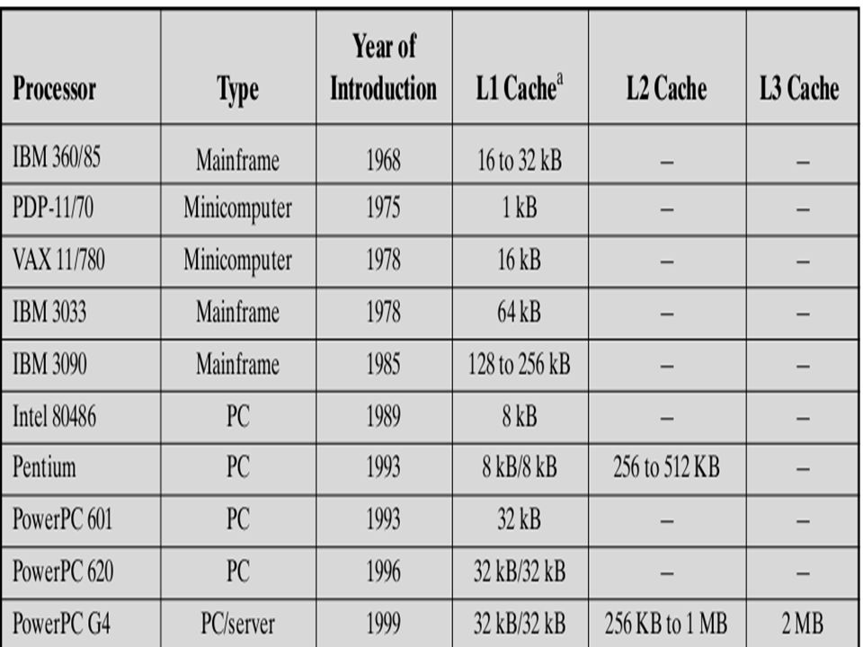
CACHE MEMORY PRINCIPLES Cache memory is intended to give memory speed approaching that of the fastest memories available, and at the same time provide a large memory size at the price of less expensive types of semiconductor memories.

17
CACHE MEMORY PRINCIPLES The cache contains a copy of portions of main memory. When the processor attempts to read a word of memory, a check is made to determine if the word is in the cache. If so, the word is delivered to the processor. If not, a block of main memory, consisting of some fixed number of words, is read into the cache and then the word is delivered to the processor.

18
CACHE MEMORY PRINCIPLES Because of the phenomenon of locality of reference, there will be future references to that same memory location or to other words in the block.

19
Structure of a cache/main-memory system Main memory consists of up to 2 power n addressable words, with each word having a unique n-bit address. For mapping purposes, this memory is considered to consist of a number of fixed-length blocks of K words each. That is, there are M= (2 power n )/K blocks in main memory. The cache consists of C lines. Each line contains K words, plus a tag of a few bits. The number of words in the line is called line size. C << M. If a word in a block of memory is read, that block is transferred to one of the lines of the cache.
/K blocks in main memory. The cache consists of C lines. Each line contains K words, plus a tag of a few bits. The number of words in the line is called line size. C << M. If a word in a block of memory is read, that block is transferred to one of the lines of the cache..")
20
Structure of a cache/main-memory system

21
Why use tag in cache? Because there are more blocks than lines, an individual line can not be uniquely and permanently dedicated to a particular block. Thus, each line includes a tag that identifies which particular block is currently being stored. The tag is usually a portion of the main memory address.

22
ILLUSTRATES THE READ OPERATION The processor generates the read address (RA) of a word to be read. If the word is contained in the cache, it is delivered to the processor. Otherwise, the block containing that word is loaded into the cache from main memory. Then the word is delivered to the processor.

23
CACHE MEMORY PRINCIPLES Cache Read Operation

24
Typical Cache Organization In this organization, the cache connects to the processor via data, control, and address lines. If the processor finds that the memory location is in the cache, a cache hit has occurred. However, if the processor does not find the memory location in the cache, a cache miss has occurred. When a cache hit occurs, the data and address buffers are disabled and communication is only between processor and cache, with no system bus traffic. When a cache miss occurs, the desired address is loaded onto the system bus and the data are returned through the data buffer to both the cache and the processor.

25
Typical Cache Organization

26
WHYs? Why address buffer is unidirectional? Why data buffer is bidirectional?

27
ELEMENTS OF CACHE DESIGN

28
ELEMENTS OF CACHE DESIGN (Cache Addresses) Processor support virtual memory. In essence, virtual memory is a facility that allows programs to address memory from a logical point of view, without regard to the amount of main memory physically available. For reads to and writes from main memory, a hardware memory management unit (MMU) translates each virtual address into a physical address in main memory.
 translates each virtual address into a physical address in main memory..")
29
ELEMENTS OF CACHE DESIGN (Cache Addresses) When virtual addresses are used, place the cache between the processor and the MMU or between the MMU and main memory. A logical cache, also known as a virtual cache, stores data using virtual addresses. The processor accesses the cache directly, without going through the MMU.

30
ELEMENTS OF CACHE DESIGN (Cache Addresses) When virtual addresses are used, place the cache between the processor and the MMU or between the MMU and main memory. A physical cache stores data using main memory physical addresses.

31
Advantages One obvious advantage of the logical cache is that cache access speed is faster than for a physical cache, because the cache can respond before the MMU performs an address translation.

32
Disadvantages The disadvantage has to do with the fact that most virtual memory systems supply each application with the same virtual memory address space. That is, each application sees a virtual memory that starts at address 0. Thus, the same virtual address in two different applications refers to two different physical addresses. The cache memory must therefore be completely flushed with each application context switch, or extra bits must be added to each line of the cache to identify which virtual address space this address refers to.

33
ELEMENTS OF CACHE DESIGN (Cache Size) Large caches tend to be slightly slower than small ones—even when built with the same integrated circuit technology and put in the same place on chip and circuit board.
 Large caches tend to be slightly slower than small ones—even when built with the same integrated circuit technology and put in the same place on chip and circuit board.")
35
ELEMENTS OF CACHE DESIGN (Mapping Function) Because there are fewer cache lines than main memory blocks, an algorithm is needed for mapping main memory blocks into cache lines. Three techniques can be used: Direct mapping Associative mapping, Set associative mapping.

36
ELEMENTS OF CACHE DESIGN (Mapping Function) For all three cases, the example includes the following elements: The cache can hold 64 KBytes. Data are transferred between main memory and the cache in blocks of 4 bytes each.This means that the cache is organized as 16K(16,000)= 2 power 14 lines of 4 bytes each. The main memory consists of 16 Mbytes, with each byte directly addressable by a 24-bit address (2 power 24 =16M). Thus, for mapping purposes, we can consider main memory to consist of 4M(40,0000) blocks of 4 bytes each.
= 2 power 14 lines of 4 bytes each. The main memory consists of 16 Mbytes, with each byte directly addressable by a 24-bit address (2 power 24 =16M). Thus, for mapping purposes, we can consider main memory to consist of 4M(40,0000) blocks of 4 bytes each..")
37
ELEMENTS OF CACHE DESIGN (Direct Mapping) The direct mapping is expressed as i = j modulo m where i = cache line number j = main memory block number m = number of lines in the cache
 The direct mapping is expressed as i = j modulo m where i = cache line number j = main memory block number m = number of lines in the cache")
38
ELEMENTS OF CACHE DESIGN (Direct Mapping) The mapping for the first m blocks of main memory. Each block of main memory maps into one unique line of the cache. The next m blocks of main memory map into the cache in the same fashion; that is, block B m of main memory maps into line L 0 of cache, block B m+1 maps into line L 1, and so on.

39
ELEMENTS OF CACHE DESIGN (Direct Mapping)
")
40
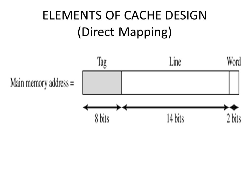
For purposes of cache access, each main memory address can be viewed as consisting of three fields. The least significant w bits identify a unique word or byte within a block of main memory. The remaining s bits specify one of the 2 power s blocks of main memory. The cache logic interprets these s bits as a tag of s-r bits (most significant portion) and a line field of r bits. This latter field identifies one of the m=2 power r lines of the cache.
 and a line field of r bits. This latter field identifies one of the m=2 power r lines of the cache..")
41
ELEMENTS OF CACHE DESIGN (Direct Mapping) To summarize,
 To summarize,")
42
ELEMENTS OF CACHE DESIGN (Direct Mapping) The effect of this mapping is that blocks of main memory are assigned to lines of the cache as follows:
 The effect of this mapping is that blocks of main memory are assigned to lines of the cache as follows:")
43
ELEMENTS OF CACHE DESIGN (Direct Mapping)
")
44
In the example, m = 16K= 2 power 14 and i= j modulo 2 power 14 The mapping becomes

45
ELEMENTS OF CACHE DESIGN ( Direct Mapping ) Note that no two blocks that map into the same line number have the same tag number. Thus, blocks with starting addresses 000000, 010000, FF0000 have tag numbers 00,01, FF, respectively. The cache system is presented with a 24-bit address. The 14-bit line number is used as an index into the cache to access a particular line. If the 8-bit tag number matches the tag number currently stored in that line, then the 2-bit word number is used to select one of the 4 bytes in that line. Otherwise, the 22-bit tag-plus-line field is used to fetch a block from main memory. The actual address that is used for the fetch is the 22-bit tag- plus-line concatenated with two 0 bits, so that 4 bytes are fetched starting on a block boundary.

46
ELEMENTS OF CACHE DESIGN (Mapping Function)
")
47
ELEMENTS OF CACHE DESIGN (Direct Mapping)
")
Similar presentations