Download presentation
Presentation is loading. Please wait.

1
Chapter 9

2
Mathematical morphology: ◦ A useful tool for extracting image components in the representation of region shape. Boundaries, skeletons, and convex hull. Set theory is usually used to describe mathematical morphology. ◦ Sets represent objects in a binary image. Black: representing object, denoted by 1. White: representing background, denoted by 0.

3
9.1 Preliminaries Our interest in this chapter is sets in Z 2, where each element denotes the coordinates of an object pixel. –If a=(a 1, a 2 ), we write if a is an element in A. – if a is not an element in A. The null or empty set is denoted by. We use braces, {·}, to specify the content of a set. For example, C={w|w=-d, for }.
, we write if a is an element in A. – if a is not an element in A. The null or empty set is denoted by. We use braces, {·}, to specify the content of a set. For example, C={w|w=-d, for }..")
4
Operations of Sets

5
Additional Definitions Translation: – Reflection: –

6
9.1.2 Logic Operations Involving Binary Images The logic operations discussed in this section involve binary images. –Black pixel: 1. –White pixel: 0. Note: logic operations are restricted to binary variables, which is not the case in general for set operations.

7
Logic Operations Involving Binary Images

8
9.2 Dilation and Erosion These two operations are fundamental to morphological processing. –Dilation: to enlarge an object along its boundary. –Erosion: to shrink an object into a smaller size.

9
9.2.1 Dilation With A and B are sets in Z 2, the dilation of A by B, denoted A B, is defined as A B = –Other interpretation: A B = B is commonly referred to as the structuring element. The dilation of A by B is the set of all displacements, z, such that the reflection of B and A overlap by at least one element.

10
The Illustration of Dilation

11
The Implementation of Dilation Given a binary image f and the structuring element s, construct a duplicate of f, denoted by g. For each pixel p = f(x, y), do the following: –If p is black: If p is at the boundary (any of the 4-adjacent neighbors is white) of the object, center the origin of s at (x, y) in g, and fill the pixels black on which s covers. Return g.
, do the following: –If p is black: If p is at the boundary (any of the 4-adjacent neighbors is white) of the object, center the origin of s at (x, y) in g, and fill the pixels black on which s covers. Return g..")
12
Application of Dilation One of the simplest applications of dilation is for bridging gaps.

13
9.2.2 Erosion With A and B are sets in Z 2, the dilation of A by B, denoted A B, is defined as A B = –The erosion of A by B is the set of all points z such that B, translated by z, is contained in A.

14
The Implementation of Dilation Given a binary image f and the structuring element s, construct a duplicate of f, denoted by g. For each pixel p = f(x, y), do the following: –If p is white: If p is adjacent to the boundary of the object, center the origin of s at (x, y) in g, and fill the pixels white on which s covers. Return g.
, do the following: –If p is white: If p is adjacent to the boundary of the object, center the origin of s at (x, y) in g, and fill the pixels white on which s covers. Return g..")
15
Application of Dilation One of the simplest uses of erosion is for eliminating irrelevant detail (in terms of size) from a binary image. Note that objects are represented by white pixels, rather than by black pixels.

16
9.3 Opening and Closing Opening: to break narrow isthmuses and to eliminate thin protrusions. Closing: to fuse narrow breaks and long thin gulfs, to eliminate small holes, and to fill gaps in the contour.

18
Illustration of Opening and Closing

19
Example 9.4: Application of Opening and Closing Example 9.4: Application of Opening and Closing

20
9.4 The Hit-or-Miss Transformation The morphological hit-or-miss transform is a basic tool for shape detection or pattern matching. Let B denote the set composed of X and its background. –B = (B 1, B 2 ), where B 1 =X, B 2 =W-X. The match of B in A, denoted by A B, is * * To find objects that may contain X To find objects that may be contained in X
, where B 1 =X, B 2 =W-X. The match of B in A, denoted by A B, is * * To find objects that may contain X To find objects that may be contained in X.")
21
The Hit-or-Miss Transformation Other interpretation: If B is 3x3, the matching can be done directly rather than computing the background image. * *

22
9.5 Some Basic Morphological Algorithms Boundary extraction Region filling Extraction of connected components Convex Hull Thinning Skeletons Pruning

23
9.5.1 Boundary Extraction The boundary of a set A, denoted by β(A), can be obtained by first eroding A by B and then performing the set difference between A and its erosion.
, can be obtained by first eroding A by B and then performing the set difference between A and its erosion.")
24
Example 9.5: Boundary Extraction Binary 1’s are shown in white and 0’s in black. Using 5x5 structuring element would result in a boundary between 2 and 3 pixels thick. The structuring element in this example is 3x3; therefore, the boundary is one pixel thick.

25
9.5.2 Region Filling Goal: given a point p inside the boundary (Fig. (a)), fill the entire region with 1’s. Let X 0 = p. The filled set X k can be obtained by
), fill the entire region with 1’s. Let X 0 = p. The filled set X k can be obtained by.")
26
The Procedure of Region Filling The algorithm terminates at iteration step k if X k =X k-1. The result is obtained from the union of X k and the boundary in A.

27
9.5.3 Extraction of Connected Components Goal: given a point p, find the component that connects to p. Let X 0 = p. The set X k can be obtained by The algorithm terminates at iteration step k if X k =X k-1. The result Y is obtained from X k.

28
The Procedure of Finding Connected Components The Procedure of Finding Connected Components

29
Example 9.7

30
9.5.4 Convex Hull A set A is said to be convex. –If the straight line joining any two points in A lies entirely within A. The convex hull H of a set S is the smallest convex set containing S. –The set H-S is called the convex difference, which is useful for object description. The procedure is to implement the equation: –With X i 0 =A. Let D i =X i conv, where “conv” indicates that X i k =X i k-1. The convex hull of A is *

31
Convex Hull

32
Limiting Growth of Convex Hull

33
9.5.5 Thinning The thinning of a set A by a structuring element B, denoted A B, is defined by Each B is usually a sequence of structuring elements: –B 1, B 2,…are different rotated versions of B. The result of thinning A by one pass is the union of the results obtained by thinning by B i by one pass. x * x

34
Thinning Procedure

35
9.5.6 Thickening The thickening of a set A by a structuring element B, denoted A B, is defined by A more efficient scheme is to obtain the complement of A, say A c, and then to compute C c, where C is the thinned result of A c and C c is its complement. · · *

36
9.5.7 Skeletons The dot line : the skeleton of A, S(A).
.")
37
The Procedure of Skeletonization

38
9.5.8 Pruning spur

39
The Procedure of Pruning Thinning an input set A to eliminate the short line segment by To restore the character to its original form: –Find the set containing all the end points by –Dilate the end points and find the intersection with A: –The union of X 3 and X 1 yields the desired result: *

40
9.6 Extensions to Gray-Scale Images Dilation –Let D f and D b be the domains of f and b, where b is the structuring element. The dilated image tends to be brighter. The dark details either reduce or eliminated, depending on their values and shapes relate to the structuring element. Erosion The eroded image tends to be darker. The bright details either reduce or eliminated.

41
Example 9.9

42
9.6.3 Opening and Closing

43
Example 9.10 In (a), the decreased sizes of the small, bright details, with no appreciable effect on the darker gray levels. In (b), the decreased sizes of the small, dark details, with relatively little effect on the bright features.
, the decreased sizes of the small, dark details, with relatively little effect on the bright features..")
44
9.6.4 Applications of Gray-Scale Morphology Morphological smoothing –i.e. performing opening followed by a closing. Morphological gradient –Let g denote the operation, and then –Depending less on edge directionality.

45
9.6.4 Applications of Gray-Scale Morphology Top-hat transformation

46
9.6.4 Applications of Gray-Scale Morphology Textural segmentation –Use closing operation to eliminate the left half. –Apply opening to restore and join the right half. –Threshold the result to draw the boundary.

47
9.6.4 Applications of Gray-Scale Morphology Granulometry ( 粒度測量 ) –Apply opening with different sizes of structuring elements. –Calculate image difference. –Draw the histogram to evaluate the difference with respect to various sizes of structuring elements. –For some x, particles with similar size of x have higher responses in the histogram.

Similar presentations
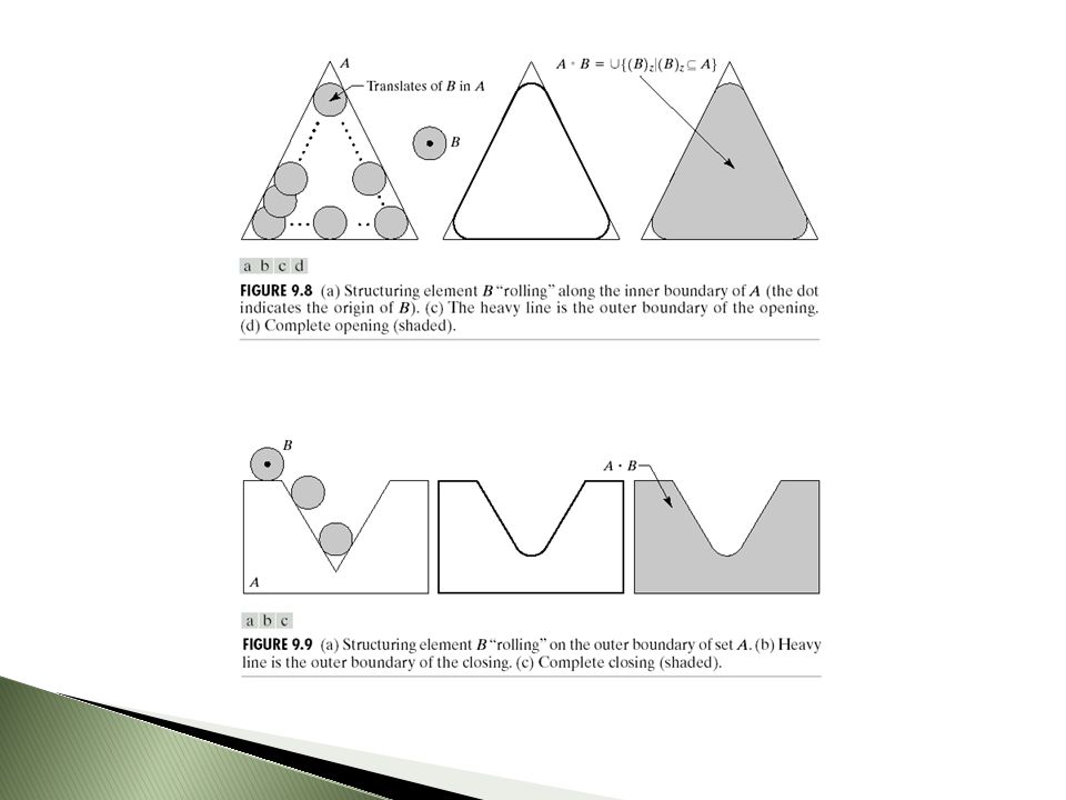


Image pre-processing.>")


 Digital Image Processing (10) 灰度的数学形态学(2) Mathematical morphology in gray scale (2) 顾 力栩 上海交通大学 计算机系 2006.6.>")
>")