Download presentation
Presentation is loading. Please wait.

1
Heavy Photon Search experiment in Hall-B slides/ideas borrowed/stolen from talks of S. Stepanyan, J. Jaros, T. Nelson Special thanks to S. Stepanyan M. Guidal, IPN Orsay

2
A heavy photon (A’) is a conjectured U(1) force particle, a massive (~100 MeV) vector boson with weak couplings to electrons. If it exists, it kinetically mix with our (SM) photon, inducing small couplings to electric charge. is expected to be of order 10 -3 m is expected ~ 10–1000 MeV (Loops of heavy particles coupling both to A’ and ) What is a “Heavy Photon”? aka “Dark Photon”, “Hidden Sector Photon”
 photon, inducing small couplings to electric charge. is expected to be of order m is expected ~ 10–1000 MeV (Loops of heavy particles coupling both to A’ and ) What is a Heavy Photon . aka Dark Photon , Hidden Sector Photon .")
3
Does Dark Matter Couple to Heavy Photons? N. Arkani-Hamed, D.P. Finkbeiner, T.R.Slayter, and N. Weiner, Phys. Rev.D79, 015014 (2009) M. Pospelov and A. Ritz, Phys. Lett. B671, 391 (2009) Observation of unexpected fluxes of e ± in the cosmic rays prompted explanations involving DM annihilation. Dark matter coupling to the A’ could explain DM annihilation into e + e – theory PAMELA e + /e - FERMI/HESS e Flux
 M. Pospelov and A. Ritz, Phys. Lett. B671, 391 (2009) Observation of unexpected fluxes of e ± in the cosmic rays prompted explanations involving DM annihilation. Dark matter coupling to the A’ could explain DM annihilation into e + e – theory PAMELA e + /e - FERMI/HESS e Flux.")
4
Fixed Target Experiments are an Ideal Hunting Ground

5
Heavy Photon Signatures A heavy photon appears as a narrow e + e - resonance on a copious background of QED tridents. The A’ lifetime depends on mass and c ~ 0.8 cm (E 0 /10 GeV) (10 -4 / ) 2 (100 MeV/m A’ ) 2 Displaced A’ decay vertices can be identified over much of the m- parameter space, distinguishing them from QED tridents. Trident Background A’ Signal Decay Length c Bump Hunt A’ Signal Trident Background **
 (10 -4 / ) 2 (100 MeV/m A’ ) 2 Displaced A’ decay vertices can be identified over much of the m- parameter space, distinguishing them from QED tridents. Trident Background A’ Signal Decay Length c Bump Hunt A’ Signal Trident Background ** .")
6
HPS Design evolved from BEST Concept J.D. Bjorken, R. Essig, P.Schuster, and N. Toro, Phys. Rev. D80, 2009,075018 A’ kinematics forward coverage required: E A’ E beam A’ 0 decay = m A’ /E A’ Want m/m ~ 1% for bump hunt Want z ~ 1mm Vertexing A’ decays requires detectors close to the target. Bump hunting needs good momentum/mass resolution. Both need tracking and a magnet. Trigger with high rate Electromagnetic Calorimeter downstream of the magnet to distinguish e + and e -. Survive beam backgrounds by spreading them out maximally in time and avoiding multiple scattered and degraded electrons Need CEBAF 100% duty cycle Need very high rate DAQ Avoid “Wall of flame” e + and e - entering ECal

7
HPS Overview Forward, compact spectrometer/vertex detector identifies heavy photon candidates with invariant mass and decay length (1T analyzing magnet). EM Calorimeter provides fast trigger and electron ID. Small cross sections and high backgrounds demand large luminosities. HPS survives beam backgrounds by spreading them out maximally in time, capitalizing on 100% CEBAF duty cycle and employing high rate DAQ. Muon detector for alternate trigger, muon ID All detectors are split above and below the beam to avoid the “wall of flame” from multiple Coulomb scattered primaries, bremsstrahlung, & degraded electrons.

8
CEBAF Beam and HPS Beamline HPS sits behind CLAS in Hall B. CEBAF meets Beam Requirements E 2.2, 6.6 GeV p/p 10 -4 I 100-1000 nA I/I < 5% x,y < 30 µm halo < 10 -5 Beam position stability (<30 µm) OK using exiting BPMs and Fast Feedback and corrector magnets. Mechanical Vibrations not a problem. Measured to be ± 2 µm on forward carriage. New optics/quads gives10 µm spots quads chicane dump Halo measured <10 -5 Expected at 12 GeV
 OK using exiting BPMs and Fast Feedback and corrector magnets. Mechanical Vibrations not a problem. Measured to be ± 2 µm on forward carriage. New optics/quads gives10 µm spots quads chicane dump Halo measured <10 -5 Expected at 12 GeV.")
9
MC Tracker Studies Radiation Damage in Layer 1 Charged Particle Occupancy ( e ± hits/cm 2 /month ) in Layer 1 Si strip detector vs height above beam Large but manageable dose on innermost strips. They remain functional up to 6 x 10 15 /cm 2 (6 mn). Occupancies are high, but manageable. Occupancy 1% beyond “dead zone” at Y = 1.5 mm (above electron beam). Dead Zone 400 nA on.25% X 0 target Sensitive Area ≥ 1.5 mm Need to confirm full GEANT4 and EGS5 Monte Carlo studies
. Occupancies are high, but manageable. Occupancy 1% beyond dead zone at Y = 1.5 mm (above electron beam). Dead Zone 400 nA on.25% X 0 target Sensitive Area ≥ 1.5 mm Need to confirm full GEANT4 and EGS5 Monte Carlo studies.")
10
MC Tracker Performance Stand-alone pattern recognition is 98% efficient in presence of realistic backgrounds. Only ~ 1 % of tracks have 1 miss-hits. Track, vertex quality, and trajectory cuts nearly eliminate vertex tails. Before quality cuts After quality cuts Tracks with miss-hits make tails Vertex Resolution along the beam direction, Z v

11
Vertex Search Trident rejection is all in the tails! Trident vertices originate in the target, Z v = 0. A’ decays can extend to large Z v. Count vertices beyond Z cut to minimize trident background. E beam = 5.5 GeV ’/ = 10 -8.5 ’/ = 10 -9.5 Vertex Distribution for m A’ = 200 MeV ± 1.25

12
MC Trigger Performance Full GEANT4 simulations are used to study trigger occupancies and rates. Occupancies OK for 8ns window and 100 MeV threshold Cluster, Energy, and Geometry cuts yield a trigger rate < 30 kHz Trigger (6.6. GeV) 2 clusters 0.5 < E 1,2 < 5.0 GeV E1 + E2 < E beam E < 4.0 GeV Co-planar Can the EM calorimeter efficiently trigger the experiment at <50kHz?
 2 clusters 0.5 < E 1,2 < 5.0 GeV E1 + E2 < E beam E < 4.0 GeV Co-planar Can the EM calorimeter efficiently trigger the experiment at <50kHz .")
13
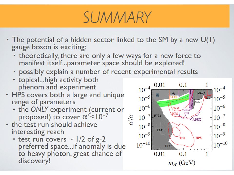
HPS Reach* 6.6 and 2.2 GeV Reach 2525 * Small changes since proposal: muons added at high masses, improving reach; low mass cut-off was about 18, now 25 MeV.

14
HPS Collaboration Jlab Hall B & Collaborators, SLAC Group, Fermilab, UCSC 16 Institutions, 58 and counting Physicists and Engineers

15
HPS Proposed Run Plan Stage I Test Run (6 GeV Era) 2 weeks installation 1 week commission 1 week data run 2.2 GeV 1-100 nA 0.125% X 0 0.6 x 10 6 s Stage II Data Runs (12 GeV Era) 1 month installation ½ month commission 2 x 3* month data runs 2.2 GeV 200 nA 0.125% X 0 9 x 10 6 s * assumes 100% efficiency 6.6 GeV 450 nA 0.25% X 0 9 x 10 6 s Install Spring 2012 before summer down for CEBAF 12 GeV Upgrade Install in CEBAF 12 GeV Era, late 2014 or 2015. Stage I Test Run approved PAC37 Approved Stage II Full HPS approved contingent on Test Run results

16
Staging a challenging experiment Key environmental questions: Can Si microstrip detectors be operated downstream of a target with manageable occupancies and without radiation damage in close proximity to an intense electron beam? Can the EM calorimeter trigger the experiment at an acceptable trigger rate (<50kHz)? Is detector performance in the presence of realistic backgrounds good enough for the physics? Two ways to answer these questions. We’ve done one. We need both! Extensive full GEANT4 and EGS5 Monte Carlo studies of trigger rates, tracker occupancies, tracker pattern recognition efficiencies and purities, and tracker and vertexing performance in the presence of backgrounds. Stage I Test Run (proposed for Spring 2012) to check MC calculations, measure occupancies and trigger rates, and exercise detector.
. Is detector performance in the presence of realistic backgrounds good enough for the physics. Two ways to answer these questions. We’ve done one. We need both. Extensive full GEANT4 and EGS5 Monte Carlo studies of trigger rates, tracker occupancies, tracker pattern recognition efficiencies and purities, and tracker and vertexing performance in the presence of backgrounds. Stage I Test Run (proposed for Spring 2012) to check MC calculations, measure occupancies and trigger rates, and exercise detector..")
17
Stage I Develops HPS Hardware, DAQ, Beams HPS Hardware, DAQ, and beams are needed to answer critical environmental questions for Stage I, but are also an essential investment in full HPS. Use existing Hall B beamline and diagnostics ( Target - 0.125% r.l. W-target (4mm), 3 wire beam profiler, additional calibration foil 0.25 r.l.). Build simplified si tracker system (20 vs 106 modules) (only stereo modules) Build new Ecal Enclosure for existing (~460) PbWO4 crystal modules. Ecal will serve for full HPS too ( Vacuum chamber between 2 parts of the ECal) Adapt existing SLAC (tracker) and Jlab (Ecal) architectures for readout and data acquisition.
, 3 wire beam profiler, additional calibration foil 0.25 r.l.). Build simplified si tracker system (20 vs 106 modules) (only stereo modules) Build new Ecal Enclosure for existing (~460) PbWO4 crystal modules. Ecal will serve for full HPS too ( Vacuum chamber between 2 parts of the ECal) Adapt existing SLAC (tracker) and Jlab (Ecal) architectures for readout and data acquisition..")
18
Layout of HPS test setup in Hall B Standard electron beam line CLAS Vacuum chamber between 2 parts of the ECal Upstream flange with feedthroughs for target and SVT controls Vacuum chamber through the magnet Photon beam dump Off axis by ~4’’

19
Beam parameters and beam line configuration Vacuum through out the system on a way of primary and scattered electrons, and bremsstrahlung photons The target and the Si-tracker installed inside a vacuum enclosure Beam profiler at the target location Photon beam dump downstream of the chicane and adequate shielding Adequate beam diagnostics for beam profile, position and current measurements and monitoring ParameterRequirementUnit E2200MeV δp/p< 10 -4 Current~ 200nA Current Instability< 5% σXσX < 300 (< 100)μm σYσY < 30 (< 100)μm Position Stability< 30μm Divergence< 100μrad Beam Halo (> 5σ)< 10 -5 Never was requested for any Hall B experiments Was not looked at this level
μm σYσY < 30 (< 100)μm Position Stability< 30μm Divergence< 100μrad Beam Halo (> 5σ)< Never was requested for any Hall B experiments Was not looked at this level")
20
CEBAF Beam Parameters Beam current measured with using SLM ( from recent Hall B run ) Typical beam size measured in Hall B ( from 2.2 GeV run ) Most of requested beam parameters are routinely delivered to Hall B CW beam, 1497 MHz bunch repetition 499 MHz/hall Beam energy 0.8 – 6 GeV, energy spread < 10 -4 At any requested current, stability < ±5% Smaller beam sizes (< 30 m) and/or very tight specs on beam position stability (< 30 m) never were requested Beam position stability, from beam profile scans, is < 50 m for X position, and < 30 m for Y X ≈50 m Y ≈90 m
 Typical beam size measured in Hall B ( from 2.2 GeV run ) Most of requested beam parameters are routinely delivered to Hall B CW beam, 1497 MHz bunch repetition 499 MHz/hall Beam energy 0.8 – 6 GeV, energy spread < At any requested current, stability < ±5% Smaller beam sizes (< 30 m) and/or very tight specs on beam position stability (< 30 m) never were requested Beam position stability, from beam profile scans, is < 50 m for X position, and < 30 m for Y X ≈50 m Y ≈90 m")
21
Optimization of beam optics Optics program “elegant” (ELEctron Generation ANd Tracking) is used to optimize Hall B beam line for 2.2 GeV (2 pass) beam at the HPS target Emittances x =1x10 -9 m-rad and y = 1x10 -9 m-rad are used as input Arne Freyberger One of the optimization runs was to get the smallest possible beam sizes in both X and Y. With the existing B-line optics, beam sizes of ~30 m is achievable Another optimization was run to get an asymmetric beam. Required beam profile X ≈250 m and Y ≈20 m is also achievable

22
Optimization of Hall B optics Optics optimization was tested during TPE run with a 2.2 GeV (2 pass) electron beam Parameters were set for a beam profile of X ≈300 m and Y ≈10 m at the Hall B ”tagger” beam profiler (~8 meters upstream of the proposed HPS target location) Several beam profile scans with different speed of wire scanner and data readout were performed to check systematics The wire scan speed was 0.1mm/s, beam motion faster than 1Hz is included in the scan. Position stability (from Y-peak position measured in various scans) < 20 m (feedback system was not initiated) X ≈280 m Y ≈20 m
 < 20 m (feedback system was not initiated) X ≈280 m Y ≈20 m.")
23
Beam line simulations GEANT4 model of the HPS beam line is ready for optimization of beam line elements (vacuum tract, flanges, photon beam dump, shielding …) Simulation is based on experience gained from TPE beam line optimization Maurizio Ungaro Exit of the last vacuum chamber Electron beam line continues in vacuum Photon beam exits to He bag to photon dump Photon beam dump
 Simulation is based on experience gained from TPE beam line optimization Maurizio Ungaro Exit of the last vacuum chamber Electron beam line continues in vacuum Photon beam exits to He bag to photon dump Photon beam dump")
24
Resources and schedule Engineering and design will be done mostly by HPS collaborators (SLAC and ORSAY) Hall B engineering group will be involved in coordinating of design and engineering efforts from contributing institutions, and in integrating of various new elements into the beam line Key personal for beam line design: at Jlab Arne Freyberger and Stepan Stepanyan, at SLAC Ken Moffeit, Marco Oriunno, Dieter Walz, and Clive Field, at Orsay Philippe Rosier and Emmanuel Rindel. For beam diagnostics and slow control: Nerses Gevorgyan (Yerevan) and Hovanes Egiyan (JLAB)
 and Hovanes Egiyan (JLAB).")
25
HPS Test Run Primary HPS Test Run Goal : measure occupancies in detector elements, Si-tracker layers and Ecal modules, positioned in close proximity to the beam plane. It requires beam transport in vacuum, working si sensors, working Ecal, and DAQ. In the process, we get valuable experience controlling beams and commissioning HPS hardware, and we get a start on HPS.

26
Secondary objectives depend on establishing useful running conditions, delivering a si system capable of track finding, and providing a fully functioning and integrated DAQ. This will let us demonstrate full HPS capability (tracker alignment, track finding efficiencies and purities,momentum and vertex resolution, trigger development,…) HPS Test Run
 HPS Test Run.")
27
Primary HPS Test Run Goal : measure occupancies in detector elements, Si-tracker layers and Ecal modules, positioned in close proximity to the beam plane. It requires beam transport in vacuum, working si sensors, working Ecal, and DAQ. In the process, we get valuable experience controlling beams and commissioning HPS hardware, and we get a start on HPS. Secondary objectives depend on establishing useful running conditions, delivering a si system capable of track finding, and providing a fully functioning and integrated DAQ. This will let us demonstrate full HPS capability (tracker alignment, track finding efficiencies and purities,momentum and vertex resolution, trigger development,…) To run the HPS test experiment there is no need for any new major beam line instrumentation. Hall B beam line is adequately equipped for this experiment. Requested beam parameters are comparable to ones routinely delivered to Hall B. Some of critical beam optics parameters are simulated and already tested, and will satisfy needs of the HPS test run. Design of new beam line elements are in progress, critical parts have workable solution. HPS Test Run
 To run the HPS test experiment there is no need for any new major beam line instrumentation. Hall B beam line is adequately equipped for this experiment. Requested beam parameters are comparable to ones routinely delivered to Hall B. Some of critical beam optics parameters are simulated and already tested, and will satisfy needs of the HPS test run. Design of new beam line elements are in progress, critical parts have workable solution. HPS Test Run.")
28
Primary HPS Test Run Goal : measure occupancies in detector elements, Si-tracker layers and Ecal modules, positioned in close proximity to the beam plane. It requires beam transport in vacuum, working si sensors, working Ecal, and DAQ. In the process, we get valuable experience controlling beams and commissioning HPS hardware, and we get a start on HPS. Secondary objectives depend on establishing useful running conditions, delivering a si system capable of track finding, and providing a fully functioning and integrated DAQ. This will let us demonstrate full HPS capability (tracker alignment, track finding efficiencies and purities,momentum and vertex resolution, trigger development,…) To run the HPS test experiment there is no need for any new major beam line instrumentation. Hall B beam line is adequately equipped for this experiment. Requested beam parameters are comparable to ones routinely delivered to Hall B. Some of critical beam optics parameters are simulated and already tested, and will satisfy needs of the HPS test run. Design of new beam line elements are in progress, critical parts have workable solution. Fully Commissioned Test Run Apparatus can do physics. * Search for heavy photons in the parameter space domain favored by a “heavy photon” explanation of the muon g-2 anomaly. * Search in the “vertexing” domain. HPS Test Run
 To run the HPS test experiment there is no need for any new major beam line instrumentation. Hall B beam line is adequately equipped for this experiment. Requested beam parameters are comparable to ones routinely delivered to Hall B. Some of critical beam optics parameters are simulated and already tested, and will satisfy needs of the HPS test run. Design of new beam line elements are in progress, critical parts have workable solution. Fully Commissioned Test Run Apparatus can do physics. * Search for heavy photons in the parameter space domain favored by a heavy photon explanation of the muon g-2 anomaly. * Search in the vertexing domain. HPS Test Run.")
30
Backups

31
HPS test setup S. Stepanyan, HPS review, March 1 (2011)31 Analyzing magnet operated at 0.5 Tm Electromagnetic Calorimeter - 460 PbWO 4 modules with APD readout in a temperature controlled enclosure, starting @ 15mrad Vacuum chamber between 2 parts of the ECal Si tracker - 5 layers, 10 stereo readout planes positioned at 15mrad from the beam plane Target - 0.125% r.l. W-target (4 m), 3 wire beam profiler, additional calibration foil 0.25 r.l. Two dipoles, operated at 0.25 Tm, to keep primary electron beam on the nominal beam axis
31 Analyzing magnet operated at 0.5 Tm Electromagnetic Calorimeter PbWO 4 modules with APD readout in a temperature controlled enclosure, 15mrad Vacuum chamber between 2 parts of the ECal Si tracker - 5 layers, 10 stereo readout planes positioned at 15mrad from the beam plane Target % r.l. W-target (4 m), 3 wire beam profiler, additional calibration foil 0.25 r.l. Two dipoles, operated at 0.25 Tm, to keep primary electron beam on the nominal beam axis.")
32
Present Limits and Region of Interest J.D. Bjorken, R. Essig, P.Schuster, and N. Toro, Phys. Rev. D80, 2009,075018 (BEST) ’/ 2’/ 2 Both “naturalness” arguments and fits to astrophysical data suggest ’/ 2 ~ 10 -4 – 10 -10 m A’ ~ MeV - GeV Both resonance-bump and separated decay vertex signatures are needed to explore this region
 ’/ 2’/ 2 Both naturalness arguments and fits to astrophysical data suggest ’/ 2 ~ – m A’ ~ MeV - GeV Both resonance-bump and separated decay vertex signatures are needed to explore this region.")
33
HPS Test Run Goals Primary HPS Test Run Goal (measuring occupancies and trigger rates) requires beam transport in vacuum, working si sensors, working Ecal, and DAQ. In the process, we get valuable experience controlling beams and commissioning HPS hardware, and we get a start on HPS. Secondary objectives depend on establishing useful running conditions, delivering a si system capable of track finding, and providing a fully functioning and integrated DAQ. This will let us demonstrate full HPS capability. * Tracker alignment * Track finding efficiencies and purities * Momentum and vertex resolution * Trigger development Modest extra expense gives greatly expanded capability Fully Commissioned Test Run Apparatus can do physics. * Search for heavy photons in the parameter space domain favored by a “heavy photon” explanation of the muon g-2 anomaly. * Search in the “vertexing” domain.

Similar presentations


 Beam Diagnostics for test facilities of i) ii) polarized e+ source January 9 –11, 2002.>")


 for precise momentum.>")
