Download presentation
Presentation is loading. Please wait.

1
Advanced Embedded Systems Design Lecture 13 RISC-CISC BAE 5030 - 003 Fall 2004 Instructor: Marvin Stone Biosystems and Agricultural Engineering Oklahoma State University

2
Goals for Class Today Questions over reading / homework Review CISC vs RISC - Ragu J1939/ISO 11783 - (Stone)
")
3
Essence of ISO 11783 an Electronics communications protocol standard –Allows manufacturers to build electronic components that communicate with each other Examples: –Instrument cluster and engine Electronic Control Unit (ECU) –Tractor ECU and Implement ECU –Grain Flow ECU and Virtual Terminal ECU –Uses multiplexed wiring ECUs communicate across a shared four wire cable Bit serial communications –Based on CAN protocol Robert Bosch GmbH protocol for automotive use
 –Tractor ECU and Implement ECU –Grain Flow ECU and Virtual Terminal ECU –Uses multiplexed wiring ECUs communicate across a shared four wire cable Bit serial communications –Based on CAN protocol Robert Bosch GmbH protocol for automotive use")
4
Network Structural Model

5
CAN based Ag related standards ISO 11783 uses pieces of J1939 and DIN 9684. At the CAN level J1939 and 11783 use the same 29 bit CAN 2.0b Mention NMEA 2000

6
Standards Bodies - Relationships ISO 11783SAE J1939

7
ISO 11783 Characteristics Attempts to Standardize communications to the extent that ECUs built by different manufacturers can communicate. Allows Ag Implement applications (precision farming apps.) Powertrain/Braking/Lighting/Instrument Panel apps. Standardized and proprietary information exchange Control loops across net (10 ms repetition) Data rate 5.6k bytes/sec. @ 30% load, bursts to 16k bytes/sec. 30 nodes per subnet, 254 nodes per system
 Powertrain/Braking/Lighting/Instrument Panel apps. Standardized and proprietary information exchange Control loops across net (10 ms repetition) Data rate 5.6k 30% load, bursts to 16k bytes/sec. 30 nodes per subnet, 254 nodes per system.")
8
Hardware review How far, how fast, how many nodes Types of nodes (if there are any). Etc. How long of a cable can we use? –Is this length a total length or from piece to piece? –Is there such a thing as a line driver, or booster? What is required in the way of line terminations?

9
J1939 / ISO 11783 Physical Layers Maximum number of ECU's –30 (per segment) ISO 11783 Media –Twisted Quad un-shielded 75 nominal impedance Two data lines (CAN_H, CAN_L) Two termination supply lines J1939-11 Media –Shielded twisted pair 120 nominal impedance Two data lines (CAN_H, CAN_L) One shield Signal –Compatable with ISO 11898 drivers (eg. Phillips 80C250) Termination –J1939 – 120 passive –ISO 11783 – Active balanced current design
 Termination –J1939 – 120 passive –ISO – Active balanced current design.")
10
Cableing Cable Cross-section

11
ISO 11783 Physical Layer Bus Fault Tolerance: –Continued communications (emissions failure?) CAN_H shorted to V bat or Ground or interrupted CAN-L shorted to V bat or Ground or interrupted –Communications Failure CAN_H Shorted to CAN_L Terminator power interrupted ECU Conformance Testing –Test specifications included
 CAN_H shorted to V bat or Ground or interrupted CAN-L shorted to V bat or Ground or interrupted –Communications Failure CAN_H Shorted to CAN_L Terminator power interrupted ECU Conformance Testing –Test specifications included")
12
Bus Length and Geometry Maximum Segment Length (L):40 m Maximum Drop Length (S):1.0 m Minimum Node Separation (d):0.1 m
:40 m Maximum Drop Length (S):1.0 m Minimum Node Separation (d):0.1 m")
13
ISO 11783 Connectors

14
Automatic Terminating Bias Connector Disconnection does not disrupt communications Provides Power and data

15
ISO 11783/J1939 Architecture ECU 1ECU 2

16
J1939 / ISO 11783 Data Link Layer - General –Based on CAN 2.0b 29 bit identifiers Defines the identifier meaning Physical Addressing ( 256 addresses) Independent priority field Data content identifier independent of sender Two message structures –Type 1 - Destination Specific - both source and destination –Type 2 - Extended - Only source address –Defines requests and acknowledgement –Defines proprietary message structure –Includes a Transport Protocol with two modes »Managed Connection »BAM
 Independent priority field Data content identifier independent of sender Two message structures –Type 1 - Destination Specific - both source and destination –Type 2 - Extended - Only source address –Defines requests and acknowledgement –Defines proprietary message structure –Includes a Transport Protocol with two modes »Managed Connection »BAM")
17
Message Capabilities Two identifier types (PDUs) –ECU to ECU –ECU to All PPPRG PDU 1 PDU 2 PPPR G Reserved First 8 Bits Between 240 and 255 Source AddressDestination Addr Page Bit TYPE Priority Parameter Group Source Address -- PDU Format --Group Extension - Parameter Group
 –ECU to ECU –ECU to All PPPRG PDU 1 PDU 2 PPPR G Reserved First 8 Bits Between 240 and 255 Source AddressDestination Addr Page Bit TYPE Priority Parameter Group Source Address -- PDU Format --Group Extension - Parameter Group")
18
PDU2 PDU1 Priority 8670 Parameter Groups can be defined 480 PDU1, 8190 PDU2 Identifier Structure

19
PGN - Parameter Group Number

20
Message Capabilities Global

21
Message Capabilities PDU1 One to One SOURCE DESTINATION -- Parameter Group -- Source Address Destination Addr. PPP

22
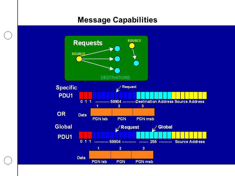
Message Capabilities

24
Reply’s to Requests

25
Message Capabilities

28
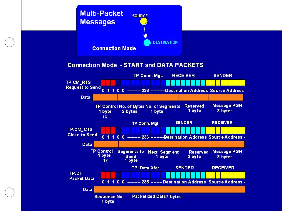
200 ms between data packets! Message Capabilities

29
Design Recommendations REQUEST SCHEDULING – The scheduling of a request should be canceled if information requested is received prior to request being sent. Parameter Groups should not be requested if they are recommended to be broadcast.

30
Design Recommendations DEVICE RESPONSE TIME AND TIME-OUT DEFAULTS –All devices, when required to provide a response, must do so within 0.20 s. All devices expecting a response must wait at least 1.25 s before giving up or retrying.

31
Design Recommendations REQUIRED RESPONSES –A response is required for a global request from all devices that have the requested PG, even the requester. Acknowledgments are not allowed for global requests. There is no restriction on minimum response time!

32
Design Recommendations CTS NUMBER OF PACKET RECOMMENDATION –During normal vehicle operation it is recommended that the maximum number of packets that can be sent per CTS be set to 16.

33
Assignment Continue: –Demonstrate sending and receiving a CAN message –Prepare Portfolio Organize with regard to milestones in course –Review each milestone –Assess your accomplishment of each milestone Include resources –Lecture materials –Outside reading – assigned and other Commented listings

Similar presentations


between two stations Addressing.>")


 BEng (Essex, UK)>")


>")

 is a product of the Open Systems Interconnection effort at the International Organization for Standardization.>")

