Download presentation
Presentation is loading. Please wait.

1
Prospective Motion Correction: Is it better? J. Andrew Derbyshire Functional MRI Core NIMH

2
Motivation MRI is a slow imaging technique – Vulnerable to motion during acquisition – Motion of 50% pixel size can yield significant artifacts

3
Motivation MRI is a slow imaging technique – Vulnerable to motion during acquisition – Motion of 50% pixel size can yield significant artifacts (Oliver Speck says it is more like 20%) Why will motion tracking be important? Higher resolution scanning – Increased scan time Increase resolution by 2x requires 64x scan time! Increased likelihood of subject motion – Smaller motions become significant

4
Sources of motion Physiological – Cardiac motion – Respiratory – Blood flow – CSF Flow – Swallowing – Coughing – Sneezing – Blinking – Peristalsis Tremors Children

5
Sources of motion Motion types: – Fast versus slow – Periodic – Continuous/sporadic – In/through plane – Local / global – Translation – Rotation – Expansion/contraction Physiological – Cardiac motion – Respiratory – Blood flow – CSF Flow – Swallowing – Coughing – Sneezing – Blinking – Peristalsis Tremors Children

6
Sources of motion Motion types: – Fast versus slow – Periodic – Continuous/sporadic – In/through plane – Local / global – Translation – Rotation – Expansion/contraction Do we need motion correction?... YES! Physiological – Cardiac motion – Respiratory – Blood flow – CSF Flow – Swallowing – Coughing – Sneezing – Blinking – Peristalsis Tremors Children

7
Effects of motion in MRI Useful to revisit the MR image acquisition process – MR image formation is based on the equation: ω = γB – In the main magnetic field, B 0, we have: ω 0 = γB 0 – Superimpose a spatial magnetic field gradient, G = (G x, G z, G z ) T then: ω = γ(B 0 + G x x + G z y + G z z) Magnetic field gradient, G x ω
 T then: ω = γ(B 0 + G x x + G z y + G z z) Magnetic field gradient, G x ω")
8
Effects of motion in MRI Useful to revisit the MR image acquisition process – MR image formation is based on the equation: ω = γB – In the main magnetic field, B 0, we have: ω 0 = γB 0 – Superimpose a spatial magnetic field gradient, G = (G x, G z, G z ) T then: ω = γG x x + G z y + G z z = G.r Magnetic field gradient, G x ω
 T then: ω = γG x x + G z y + G z z = G.r Magnetic field gradient, G x ω")
9
Effects of motion in MRI Consider the green blob of tissue So, the signal from the whole slice is: Write: To obtain the MRI signal equations Magnetic field gradient, G x ω

10
Effects of motion in MRI MR image acquisition revisited MR image formation assumes that spins are not moving. Frequency encodingPhase encoding

11
Effects of motion in MRI MRI scans typically comprise multiple repetitions – Each repetition of the basic pulse sequence is separated by TR – Phase encode steps (or similar) Useful to distinguish between motion time-scales: – intra-TR : i.e. motion within each measurement – inter-TR : i.e. motion across / between measurements

12
Intra-TR motion and Gradients MR image formation is based on the equation: ω = γB In the main magnetic field, B 0, we have: ω 0 = γB 0 Superimpose a spatial magnetic field gradient, G = (G x, G z, G z ) T then: ω = γG x x + G z y + G z z = G.r Magnetic field gradient, G x ω
 T then: ω = γG x x + G z y + G z z = G.r Magnetic field gradient, G x ω")
13
Intra-TR motion and Gradients Moving spins: Accumulated phase in presence of gradient: In particular, for uniform motion: r(t) = r 0 + v 0 t, we have additional phase: Φ = m 0.r 0 + m 1.v 0 where m 1 is the first moment of the gradient waveform.
 = r 0 + v 0 t, we have additional phase: Φ = m 0.r 0 + m 1.v 0 where m 1 is the first moment of the gradient waveform.")
14
Intra-TR motion Motion within a TR – undesired velocity-proportional phase accumulation – Φ = m 0.r 0 + m 1.v 0 For complex / dispersive motions – e.g. complex flows, rotational flow, high shear, turbulence – multiple velocities present within a single voxel – phase cancellation – signal dropout

15
Inter-TR motion Motion that varies between TRs will – cause phase changes from one TR to the next (gradient m1 effect) – possibly cause amplitude changes (e.g.) through plane motion This causes modulations of the expected MRI signal in the phase encoding direction, resulting in motion artifacts. Artifacts are always in the phase encode direction! – independent of the actual direction of motion Periodic / pulsatile motions (e.g. blood flow) causes ghosting artifacts
 causes ghosting artifacts.")
16
Flow Ghosting Provides an elegant geometric description of the flow ghost formation MRM 19:422:1993

17
Motion Correction Strategies Non-motion tracking – Immobilization – Signal averaging – Saturation bands – Gradient moment nulling – short TE – k-space trajectory radial spiral Motion tracked – ECG / respiratory gating – View re-ordering (e.g. ROPE) – Navigator acquisitions – self-navigated – propeller – Slice tracking – MR based – Optical – Other In practice, available methods and choices are application dependent
 – Navigator acquisitions – self-navigated – propeller – Slice tracking – MR based – Optical – Other In practice, available methods and choices are application dependent.")
18
Periodic motion Cardiac motion – ECG/Plethysmograph/Acoustic cardiac signal – Triggering : Wait for trigger, then scan – Gating : scan until trigger

19
Prospective Motion Correction Track scan-plane with patient motion –track scan-plane with subject motion –reduced motion artifacts Two steps: –Detecting and measuring the motion –Real-time scan plane updating Imaging Parameters MRI Scan Measure Motion Free Images

20
Prospective Motion Correction Multiple approaches to position measurement are possible – MR based navigator echoes – MR based external tracking – Optical based tracking – Other methods Imaging scan-plane feedback: similar for all approaches – Typically model motion as rigid body – Global motion model for whole image

21
Motion Correction: what is possible? Translation Rotation Stretching Shearing Phase roll modulation Rotation Compression Orthogonal shearing MR scanning is performed in k-space

22
Motion Correction: what is possible? MR scanning is performed in k-space Rigid body motion – Global motion model for whole subject – 6 parameters 3 translational 3 rotational Translation Rotation Stretching Shearing Phase roll modulation Rotation Compression Orthogonal shearing

23
Motion Correction: what is possible? MR scanning is performed in k-space Rigid body motion – Global motion model for whole subject – 6 parameters 3 translational 3 rotational Non-rigid body motion corrections are very difficult Translation Rotation Stretching Shearing Phase roll modulation Rotation Compression Orthogonal shearing

24
Rigid body scan plane update For a Cartesian (phase encoded) sequence, the scan plane update [ R, (r, p, s) ] is applied as changes to: Update to image plane rotation matrix: – Defines read, phase and slice directions in terms of magnet X, Y, Z Slice/slab selective RF pulse frequency: – Translates scan-plane to the new image center in the new slice direction – ω slice = Υg slice s Readout frequency: – Effects FOV shift to the new image center in the new readout direction – ω readout = Υg readout r Readout phase: – Effects FOV shift to the new image center in the new PE direction – θ = 2π (p / FOV phase ) PE step
![Rigid body scan plane update For a Cartesian (phase encoded) sequence, the scan plane update [ R, (r, p, s) ] is applied as changes to: Update to image plane rotation matrix: – Defines read, phase and slice directions in terms of magnet X, Y, Z Slice/slab selective RF pulse frequency: – Translates scan-plane to the new image center in the new slice direction – ω slice = Υg slice s Readout frequency: – Effects FOV shift to the new image center in the new readout direction – ω readout = Υg readout r Readout phase: – Effects FOV shift to the new image center in the new PE direction – θ = 2π (p / FOV phase ) PE step](http://images.slideplayer.com/24/7374295/slides/slide_24.jpg "Rigid body scan plane update For a Cartesian (phase encoded) sequence, the scan plane update [ R, (r, p, s) ] is applied as changes to: Update to image plane rotation matrix: – Defines read, phase and slice directions in terms of magnet X, Y, Z Slice/slab selective RF pulse frequency: – Translates scan-plane to the new image center in the new slice direction – ω slice = Υg slice s Readout frequency: – Effects FOV shift to the new image center in the new readout direction – ω readout = Υg readout r Readout phase: – Effects FOV shift to the new image center in the new PE direction – θ = 2π (p / FOV phase ) PE step")
25
Rigid body scan plane update For a Cartesian (phase encoded) sequence, the scan plane update [ R, (r, p, s) ] is applied as changes to: Update to image plane rotation matrix: – Defines read, phase and slice directions in terms of magnet X, Y, Z Slice/slab selective RF pulse frequency: – Translates scan-plane to the new image center in the new slice direction – ω slice = Υg slice s Readout frequency: – Effects FOV shift to the new image center in the new readout direction – ω readout = Υg readout r Readout phase: – Effects FOV shift to the new image center in the new PE direction – θ = 2π (p / FOV phase ) PE step Note that no changes to gradient waveforms are required!
![Rigid body scan plane update For a Cartesian (phase encoded) sequence, the scan plane update [ R, (r, p, s) ] is applied as changes to: Update to image plane rotation matrix: – Defines read, phase and slice directions in terms of magnet X, Y, Z Slice/slab selective RF pulse frequency: – Translates scan-plane to the new image center in the new slice direction – ω slice = Υg slice s Readout frequency: – Effects FOV shift to the new image center in the new readout direction – ω readout = Υg readout r Readout phase: – Effects FOV shift to the new image center in the new PE direction – θ = 2π (p / FOV phase ) PE step Note that no changes to gradient waveforms are required!](http://images.slideplayer.com/24/7374295/slides/slide_25.jpg "Rigid body scan plane update For a Cartesian (phase encoded) sequence, the scan plane update [ R, (r, p, s) ] is applied as changes to: Update to image plane rotation matrix: – Defines read, phase and slice directions in terms of magnet X, Y, Z Slice/slab selective RF pulse frequency: – Translates scan-plane to the new image center in the new slice direction – ω slice = Υg slice s Readout frequency: – Effects FOV shift to the new image center in the new readout direction – ω readout = Υg readout r Readout phase: – Effects FOV shift to the new image center in the new PE direction – θ = 2π (p / FOV phase ) PE step Note that no changes to gradient waveforms are required!")
26
Prospective tracking using MR markers JMRI 8:924, 1998 Patent: US 5947900 Track scan-plane with patient motion –Keep ROI in scan-plane –track scan-plane with surgical instrument –reduced motion artifacts

27
MR-based position tracking Small RF locator coil for identifying position – 2mm i.d. solenoidal tuned MR coil – Internal spherical sample (doped water) MR signal with frequency, Magnetic field gradient, G B1 profile x Locator coil position Dumoulin et al. MRM 29:411:1993
 MR signal with frequency, Magnetic field gradient, G B1 profile x Locator coil position Dumoulin et al. MRM 29:411:1993.")
28
Position Measurement Gradient echo – excite sample and read out signal from RF coil – signal at characteristic frequency, Signal analysis – centre frequency provides position: = Gx Repeat process – for G in x, y and z directions to find 3D position of locator coil RF G read signal 1D Position measurement analysis G dephase

29
Position Measurement Local B0 inhomogeneities: – offset frequency: ’ Acquire 4 gradient echoes directed tetrahedrally Hadamard encoding scheme: x = ’ D1 + ’ D2 - ’ D3 - ’ D4 y = ’ D1 - ’ D2 + ’ D3 - ’ D4 z = ’ D1 - ’ D2 - ’ D3 + ’ D4 Eliminates spurious term X Y Z D1 = ( 1, 1, 1) D2 = ( 1, -1, -1) D3 = (-1, 1, -1) D4 = (-1, -1, 1) Dumoulin et al. MRM 29:411:1993

30
Scan-plane tracking Three or more position markers (e.g. triangle) fixed to subject – At least three non-colinear markers are required identify rigid body motion Define local co-ordinate system relative to triangle Define position & orientation of scan-plane in local co-ordinate system Scan-plane tracking: – Update rotation matrix – Update slice frequency and phase – Update readout frequency and phase – Update phase encode (per PE line) frequency and phase x y z MR scan-plane Reference triangle
 fixed to subject – At least three non-colinear markers are required identify rigid body motion Define local co-ordinate system relative to triangle Define position & orientation of scan-plane in local co-ordinate system Scan-plane tracking: – Update rotation matrix – Update slice frequency and phase – Update readout frequency and phase – Update phase encode (per PE line) frequency and phase x y z MR scan-plane Reference triangle.")
31
Results Phantom study photouncorrectedcorrected Images of standard phantom Object moved between successive imaging scans Tracking system provides images from the same section of the object 1 2 3 4

32
Results Human head photouncorrectedcorrected Transverse images of brain of human volunteer Subject requested to move between scans Tracking system provides images from the same section of the subject 1 2 3 4

33
Prospective tracking using MR markers Intra-image scan-plane updates – once per full image scan – Slow-tracking for GRE type scans, OK for EPI Inter-image scan-plane updates – OK for small motions – B0 non-uniformity – changes phase mid scan – B1 non-uniformity – changes phase mid scan Precision – Position measurements ~ 0.1mm – Rotation/Tilting Slice distance from reference markers – Angular amplification of errors. Need triangle to be close to scan-plane of interest Time required for MR position measurement (15-20ms)
.")
34
Wireless RF micro-coils Inductive coupling with head coil Microcoil is de-tuned during RF transmit Huge Rx signal enhancement from marker sample in the microcoil

35
MR based image tracking 3 orthogonal 2D navigators with Kalman filter based motion estimation MRM 63:91:2010

36
PROMO Sequence Design: Spiral tracker: 3 spiral AQs:3x 14ms Flip:8° Voxel size:1cm 3 Reconstruction:3x 2ms TR spiral-tracker :100ms Repeat J=5 times:500ms Requires time for Navigator AQ, reconstruction and tracking calculations Useful for inversion recovery (T IR = ~1100ms) Less useful for non magnetization prepared sequences Must use low flip angle to avoid spin-history effects during IR time Can be compared to other MR super-navigators methods EPI based instead of spiral Orbital navigators Cloverleaf, etc.
 Less useful for non magnetization prepared sequences Must use low flip angle to avoid spin-history effects during IR time Can be compared to other MR super-navigators methods EPI based instead of spiral Orbital navigators Cloverleaf, etc.")
37
PROMO Spiral nav images:10mm x 10mm x10mm 3x14ms total AQ time for tracking sequences 100ms for AQ, recon & tracking calculations etc.

38
PROMO at NIH Multi-echo MP-RAGE implementation (Vinai Roopc) – Available on GE 3T scanners (3TA, 3TB, 3TC) – Appears to be working well – See e.g. their 2014 ISMRM Motion Workshop poster MP2-Rage version (Alexandru Avram) – Available on 3TC
 – Available on 3TC.")
39
Prospective tracking using stereo optical system MRM 62:924:2009

40
Prospective tracking using stereo optical system Additional calibration of camera with MR system required – Not required for MR based tracking Camera mounted on coil – table motion Accuracy: – 0.1mm translation – 0.15° rotation Tracking rate: 10Hz

41
Prospective tracking using stereo optical system 7T GE system 0.2mm x 0.2mm x 3mm Sudden stepwise motion Gradual motion

42
Kineticor system Evaluating system on FMRIF 3TD (Siemens) Camera mounted on top side of bore MR system calibration patch mounted on bottom of bore Marker for Moiré phase tracking
 Camera mounted on top side of bore MR system calibration patch mounted on bottom of bore Marker for Moiré phase tracking")
43
Kineticor system Evaluating system on FMRIF 3TD (Siemens) 3 minute MP-RAGE scan Motion correction onMotion correction off
 3 minute MP-RAGE scan Motion correction onMotion correction off")
44
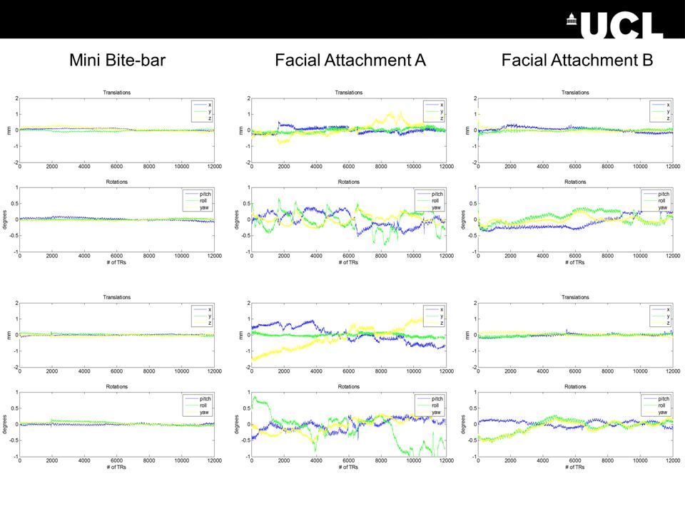
Kineticor system The UCL group investigated multiple approaches to marker fixation: – Direct-to-skin – Nose-clip – Glasses – Toothclip mounting required 32 channel headcoil Callaghan, Todd: UCL group

46
Other systems

47
Discussion Rigid body motion model – difficult to generalize to more complex motions types – Unable to correct local motion (e.g. tongue, eyes, etc.) Latency of scan-plane feedback – Tracking calculation – Sequence update (MRI pulse sequence frame length) Requires specially modified pulse sequence – to handle real-time imaging parameter feedback – vendors may develop an API to support these concepts Fixation of external markers for MR or optical tracking – markers on skin can move – limited visual FOV of camera with 32-channel head coil etc. MR tracking systems usually reduce scanning efficiency Optical systems need additional camera/MR calibration Verification – PMC changes the acquisition – non-corrected image is not acquired – PMC failure often makes the images much worse!
 Latency of scan-plane feedback – Tracking calculation – Sequence update (MRI pulse sequence frame length) Requires specially modified pulse sequence – to handle real-time imaging parameter feedback – vendors may develop an API to support these concepts Fixation of external markers for MR or optical tracking – markers on skin can move – limited visual FOV of camera with 32-channel head coil etc. MR tracking systems usually reduce scanning efficiency Optical systems need additional camera/MR calibration Verification – PMC changes the acquisition – non-corrected image is not acquired – PMC failure often makes the images much worse!.")
48
Prospective Motion Correction Is it better? Maybe – at least for applications where it is reasonable to assume rigid body motion Given the demands of high (i.e better than 0.5mm isotropic) resolution, we will probably need to use all the available tricks in our MR toolbox. A very active area of research at the moment: – MRM review article 2012 – MRM virtual issue – ISMRM workshop, 2014
 resolution, we will probably need to use all the available tricks in our MR toolbox. A very active area of research at the moment: – MRM review article 2012 – MRM virtual issue – ISMRM workshop,")
49
Thanks for your attention

Similar presentations


>")


 degrades with slice offset and slice thickness when Z2 SEM is used in GradLoc imaging (ROI = FOV/2). To recover the full.>")


