Download presentation
Presentation is loading. Please wait.

1
Electromagnetic Induction
Chapter 29 opener. One of the great laws of physics is Faraday’s law of induction, which says that a changing magnetic flux produces an induced emf. This photo shows a bar magnet moving inside a coil of wire, and the galvanometer registers an induced current. This phenomenon of electromagnetic induction is the basis for many practical devices, including generators, alternators, transformers, tape recording, and computer memory.

2
Induced EMF Faraday’s Law of Induction; Lenz’s Law EMF Induced in a Moving Conductor Electric Generators Back EMF and Counter Torque; Eddy Currents

3
Transformers and Transmission of Power
A Changing Magnetic Flux Produces an Electric Field Applications of Induction: Sound Systems, Computer Memory, Seismograph

4
Induced EMF Almost 200 years ago, Faraday looked for evidence that a magnetic field would induce an electric current with this apparatus: Figure Faraday’s experiment to induce an emf.

5
Induced EMF He found no evidence when the current was steady, but did see a current induced when the switch was turned on or off. Figure (a) A current is induced when a magnet is moved toward a coil, momentarily increasing the magnetic field through the coil. (b) The induced current is opposite when the magnet is moved away from the coil ( decreases). Note that the galvanometer zero is at the center of the scale and the needle deflects left or right, depending on the direction of the current. In (c), no current is induced if the magnet does not move relative to the coil. It is the relative motion that counts here: the magnet can be held steady and the coil moved, which also induces an emf.
 A current is induced when a magnet is moved toward a coil, momentarily increasing the magnetic field through the coil. (b) The induced current is opposite when the magnet is moved away from the coil ( decreases). Note that the galvanometer zero is at the center of the scale and the needle deflects left or right, depending on the direction of the current. In (c), no current is induced if the magnet does not move relative to the coil. It is the relative motion that counts here: the magnet can be held steady and the coil moved, which also induces an emf.")
6
Induced EMF Therefore, a changing magnetic field induces an emf.
Faraday’s experiment used a magnetic field that was changing because the current producing it was changing; the previous graphic shows a magnetic field that is changing because the magnet is moving.

7
Magnetic Flux The induced emf in a wire loop is proportional to the rate of change of magnetic flux through the loop. Magnetic flux: Unit of magnetic flux: weber, Wb: 1 Wb = 1 T·m2.

8
Magnetic Flux This drawing shows the variables in the flux equation:
Figure Determining the flux through a flat loop of wire. This loop is square, of side l and area A = l2.

9
Magnetic Flux The magnetic flux is analogous to the electric flux – it is proportional to the total number of magnetic field lines passing through the loop. Figure Magnetic flux ΦB is proportional to the number of lines of B that pass through the loop.

10
Magnetic Flux Determining flux.
A square loop of wire encloses area A1. A uniform magnetic field B perpendicular to the loop extends over the area A2. What is the magnetic flux through the loop A1? Solution: Assuming the field is zero outside A2, the flux is BA2.

11
Faraday’s Law of Induction
Faraday’s law of induction: the emf induced in a circuit is equal to the rate of change of magnetic flux through the circuit: or

12
Faraday’s Law of Induction
A loop of wire in a magnetic field. A square loop of wire of side l = 5.0 cm is in a uniform magnetic field B = 0.16 T. What is the magnetic flux in the loop (a) when B is perpendicular to the face of the loop and (b) when B is at an angle of 30° to the area A of the loop? (c) What is the magnitude of the average current in the loop if it has a resistance of Ω and it is rotated from position (b) to position (a) in 0.14 s? Solution: a. The flux is BA = 4.0 x 10⁻⁴ Wb. b. The flux is BA cos θ = 3.5 x 10⁻⁴ Wb. c. The emf is ΔΦB/Δt = 3.6 x 10⁻⁴ V; then I = emf/R = 30 mA.
 when B is perpendicular to the face of the loop and (b) when B is at an angle of 30° to the area A of the loop (c) What is the magnitude of the average current in the loop if it has a resistance of Ω and it is rotated from position (b) to position (a) in 0.14 s Solution: a. The flux is BA = 4.0 x 10⁻⁴ Wb. b. The flux is BA cos θ = 3.5 x 10⁻⁴ Wb. c. The emf is ΔΦB/Δt = 3.6 x 10⁻⁴ V; then I = emf/R = 30 mA.")
13
Faraday’s Law of Induction; Lenz’s Law
The minus sign gives the direction of the induced emf: A current produced by an induced emf moves in a direction so that the magnetic field it produces tends to restore the changed field. or: An induced emf is always in a direction that opposes the original change in flux that caused it.

14
Faraday’s Law of Induction
Magnetic flux will change if the area of the loop changes. Figure A current can be induced by changing the area of the coil, even though B doesn’t change. Here the area is reduced by pulling on its sides: the flux through the coil is reduced as we go from (a) to (b). Here the brief induced current acts in the direction shown so as to try to maintain the original flux (Φ = BA) by producing its own magnetic field into the page. That is, as the area A decreases, the current acts to increase B in the original (inward) direction.
 to (b). Here the brief induced current acts in the direction shown so as to try to maintain the original flux (Φ = BA) by producing its own magnetic field into the page. That is, as the area A decreases, the current acts to increase B in the original (inward) direction.")
15
Faraday’s Law of Induction
Magnetic flux will change if the angle between the loop and the field changes. Figure A current can be induced by rotating a coil in a magnetic field. The flux through the coil changes from (a) to (b) because θ (in Eq. 29–1a, Φ = BA cos θ) went from 0° (cos θ = 1) to 90° (cos θ = 0).
 to (b) because θ (in Eq. 29–1a, Φ = BA cos θ) went from 0° (cos θ = 1) to 90° (cos θ = 0).")
16
Faraday’s Law of Induction
Induction stove. In an induction stove, an ac current exists in a coil that is the “burner” (a burner that never gets hot). Why will it heat a metal pan but not a glass container? Solution: The magnetic field created by the current induces a current in the metal pan, which heats due to resistance. Very little current is induced in a glass pan (or in your hand, which is why it does not feel hot).
. Why will it heat a metal pan but not a glass container Solution: The magnetic field created by the current induces a current in the metal pan, which heats due to resistance. Very little current is induced in a glass pan (or in your hand, which is why it does not feel hot).")
17
Lenz’s Law Problem Solving: Lenz’s Law
Determine whether the magnetic flux is increasing, decreasing, or unchanged. The magnetic field due to the induced current points in the opposite direction to the original field if the flux is increasing; in the same direction if it is decreasing; and is zero if the flux is not changing. Use the right-hand rule to determine the direction of the current. Remember that the external field and the field due to the induced current are different.

18
Lenz’s Law Practice with Lenz’s law.
In which direction is the current induced in the circular loop for each situation? Solution: a. Pulling the loop to the right out of a magnetic field which points out of the page. The flux through the loop is outward and decreasing; the induced current will be counterclockwise. b. Shrinking a loop in a magnetic field pointing into the page. The flux through the loop is inward and decreasing; the induced current will be clockwise. c. N magnetic pole moving toward the loop into the page. The flux through the loop is inward and increasing; the induced current will be counterclockwise. d. N magnetic pole moving toward loop in the plane of the page. There is no flux through the loop, and no induced current. e. Rotating the loop by pulling the left side toward us and pushing the right side in; the magnetic field points from right to left. The flux through the loop is to the left and increasing; the induced current will be counterclockwise.

19
Faraday’s Law of Induction; Lenz’s Law
Pulling a coil from a magnetic field. A 100-loop square coil of wire, with side l = 5.00 cm and total resistance 100 Ω, is positioned perpendicular to a uniform T magnetic field. It is quickly pulled from the field at constant speed (moving perpendicular to B) to a region where B drops abruptly to zero. At t = 0, the right edge of the coil is at the edge of the field. It takes s for the whole coil to reach the field-free region. Find (a) the rate of change in flux through the coil, and (b) the emf and current induced. (c) How much energy is dissipated in the coil? (d) What was the average force required (Fext)? Solution: a. The flux goes from BA to zero in s, so ΦB/ t = BA/t = x 10-2 Wb/s. b. The emf is –N ΦB/ dt = 1.50 V. The current is emf/R = 15.0 mA. c. E = Pt = I2Rt = 2.25 x 10⁻³ J. d. F = W/d = N.
 to a region where B drops abruptly to zero. At t = 0, the right edge of the coil is at the edge of the field. It takes s for the whole coil to reach the field-free region. Find (a) the rate of change in flux through the coil, and (b) the emf and current induced. (c) How much energy is dissipated in the coil (d) What was the average force required (Fext) Solution: a. The flux goes from BA to zero in s, so ΦB/ t = BA/t = x 10-2 Wb/s. b. The emf is –N ΦB/ dt = 1.50 V. The current is emf/R = 15.0 mA. c. E = Pt = I2Rt = 2.25 x 10⁻³ J. d. F = W/d = N.")
20
EMF Induced in a Moving Conductor
This image shows another way the magnetic flux can change: Figure 29-12a. A conducting rod is moved to the right on a U-shaped conductor in a uniform magnetic field B that points out of the page. The induced current is clockwise.

21
EMF Induced in a Moving Conductor
Force on the rod. To make the rod move to the right at speed v, you need to apply an external force on the rod to the right. (a) Explain and determine the magnitude of the required force. (b) What external power is needed to move the rod? Solution: a. The external force needs to be equal and opposite to the magnetic force (IlB) if the rod is to move at a constant speed. I = Blv/R, so F = B2l2v/R. b. The external power is Fv = B2l2v2/R, which is equal to the power dissipated in the resistance of the rod (I2R).
 Explain and determine the magnitude of the required force. (b) What external power is needed to move the rod Solution: a. The external force needs to be equal and opposite to the magnetic force (IlB) if the rod is to move at a constant speed. I = Blv/R, so F = B2l2v/R. b. The external power is Fv = B2l2v2/R, which is equal to the power dissipated in the resistance of the rod (I2R).")
22
Electric Generators A generator is the opposite of a motor – it transforms mechanical energy into electrical energy. This is an ac generator: The axle is rotated by an external force such as falling water or steam. The brushes are in constant electrical contact with the slip rings. Figure An ac generator.

23
Electric Generators If the loop is rotating with constant angular velocity ω, the induced emf is sinusoidal: For a coil of N loops, Figure An ac generator produces an alternating current. The output emf E = E0 sin ωt, where E0 = NABω.

24
Electric Generators An ac generator.
The armature of a 60-Hz ac generator rotates in a 0.15-T magnetic field. If the area of the coil is 2.0 x 10⁻² m2, how many loops must the coil contain if the peak output is to be %0 = 170 V? Solution: N = E0/BAω = 150 turns. Remember to convert 60 Hz to angular units.

25
Electric Generators A dc generator is similar, except that it has a split-ring commutator instead of slip rings. Figure (a) A dc generator with one set of commutators, and (b) a dc generator with many sets of commutators and windings.
 A dc generator with one set of commutators, and (b) a dc generator with many sets of commutators and windings.")
26
Electric Generators Automobiles now use alternators rather than dc generators, to reduce wear. Figure (a) Simplified schematic diagram of an alternator. The input current to the rotor from the battery is connected through continuous slip rings. Sometimes the rotor electromagnet is replaced by a permanent magnet. (b) Actual shape of an alternator. The rotor is made to turn by a belt from the engine. The current in the wire coil of the rotor produces a magnetic field inside it on its axis that points horizontally from left to right, thus making north and south poles of the plates attached at either end. These end plates are made with triangular fingers that are bent over the coil—hence there are alternating N and S poles quite close to one another, with magnetic field lines between them as shown by the blue lines. As the rotor turns, these field lines pass through the fixed stator coils (shown on the right for clarity, but in operation the rotor rotates within the stator), inducing a current in them, which is the output.
 Simplified schematic diagram of an alternator. The input current to the rotor from the battery is connected through continuous slip rings. Sometimes the rotor electromagnet is replaced by a permanent magnet. (b) Actual shape of an alternator. The rotor is made to turn by a belt from the engine. The current in the wire coil of the rotor produces a magnetic field inside it on its axis that points horizontally from left to right, thus making north and south poles of the plates attached at either end. These end plates are made with triangular fingers that are bent over the coil—hence there are alternating N and S poles quite close to one another, with magnetic field lines between them as shown by the blue lines. As the rotor turns, these field lines pass through the fixed stator coils (shown on the right for clarity, but in operation the rotor rotates within the stator), inducing a current in them, which is the output.")
27
Back EMF and Counter Torque
An electric motor turns because there is a torque on it due to the current. We would expect the motor to accelerate unless there is some sort of drag torque. That drag torque exists, and is due to the induced emf, called a back emf.

28
Back EMF and Counter Torque
Back emf in a motor. The armature windings of a dc motor have a resistance of 5.0 Ω. The motor is connected to a 120-V line, and when the motor reaches full speed against its normal load, the back emf is 108 V. Calculate (a) the current into the motor when it is just starting up, and (b) the current when the motor reaches full speed. Solution: a. At startup, I = V/R = 24 A. b. The back emf means that the total emf in the circuit is 12 V, so the current is 2.4 A.
 the current into the motor when it is just starting up, and (b) the current when the motor reaches full speed. Solution: a. At startup, I = V/R = 24 A. b. The back emf means that the total emf in the circuit is 12 V, so the current is 2.4 A.")
29
Back EMF and Counter Torque
Motor overload. When using an appliance such as a blender, electric drill, or sewing machine, if the appliance is overloaded or jammed so that the motor slows appreciably or stops while the power is still connected, the device can burn out and be ruined. Explain why this happens. The motor is designed to operate at a particular speed, which means there will be a particular back emf. If the appliance slows or stops, the back emf becomes much less, the current becomes much more than designed, and the appliance may burn out.

30
Back EMF and Counter Torque
A similar effect occurs in a generator – if it is connected to a circuit, current will flow in it, and will produce a counter torque. This means the external applied torque must increase to keep the generator turning.

31
Eddy Currents Induced currents can flow in bulk material as well as through wires. These are called eddy currents, and can dramatically slow a conductor moving into or out of a magnetic field. Figure Production of eddy currents in a rotating wheel. The grey lines in (b) indicate induced current.
 indicate induced current.")
32
Origins of Induced EMFs
Emf is the work done per unit charge by the source: Induced electric fields Motional emf

33
Motional EMF The induced current is in a direction that tends to slow the moving bar – it will take an external force to keep it moving. Figure 29-12b. Upward force on an electron in the metal rod (moving to the right) due to B pointing out of the page.
 due to B pointing out of the page.")
35
EMF Induced in a Moving Conductor
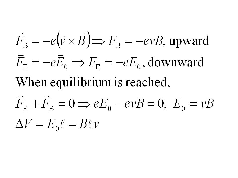
The induced emf has magnitude This equation is valid as long as B, l, and v are mutually perpendicular (if not, it is true for their perpendicular components).
.")
36
Motional EMF Does a moving airplane develop a large emf?
An airplane travels 1000 km/h in a region where the Earth’s magnetic field is about 5 x 10⁻⁵ T and is nearly vertical. What is the potential difference induced between the wing tips that are 70 m apart? Solution: E = Blv = 1 V.

37
Induced Electric Fields
E produced by changing B. A magnetic field B between the pole faces of an electromagnet is nearly uniform at any instant over a circular area of radius r0. The current in the windings of the electromagnet is increasing in time so that B changes in time at a constant rate dB/dt at each point. Beyond the circular region (r > r0), we assume B = 0 at all times. Determine the electric field E at any point P a distance r from the center of the circular area due to the changing B. Figure (a) Side view of nearly constant B. (b) Top view, for determining the electric field E at point P. (c) Lines of E produced by increasing B (pointing outward). (d) Graph of E vs. r. Example 29–14. Solution: Because of symmetry, E will be perpendicular to B and constant at radius r. Integrate around a circle of radius r as shown. For r < r0, the enclosed flux is Bπr2, and E = r/2 dB/dt. For r > r0, the enclosed flux is Bπr02, and E = r02/2r dB/dt.
, we assume B = 0 at all times. Determine the electric field E at any point P a distance r from the center of the circular area due to the changing B. Figure (a) Side view of nearly constant B. (b) Top view, for determining the electric field E at point P. (c) Lines of E produced by increasing B (pointing outward). (d) Graph of E vs. r. Example 29–14. Solution: Because of symmetry, E will be perpendicular to B and constant at radius r. Integrate around a circle of radius r as shown. For r < r0, the enclosed flux is Bπr2, and E = r/2 dB/dt. For r > r0, the enclosed flux is Bπr02, and E = r02/2r dB/dt.")
38
Applications of Induction: Sound Systems, Computer Memory, Seismograph
This microphone works by induction; the vibrating membrane induces an emf in the coil. Figure Diagram of a microphone that works by induction.

39
Applications of Induction: Sound Systems, Computer Memory, Seismograph
Differently magnetized areas on an audio tape or disk induce signals in the read/write heads. Figure (a) Read/Write (playback/recording) head for tape or disk. In writing or recording, the electric input signal to the head, which acts as an electromagnet, magnetizes the passing tape or disk. In reading or playback, the changing magnetic field of the passing tape or disk induces a changing magnetic field in the head, which in turn induces in the coil an emf that is the output signal. (b) Photo of a hard drive showing several platters and read/write heads that can quickly move from the edge of the disk to the center.
 Read/Write (playback/recording) head for tape or disk. In writing or recording, the electric input signal to the head, which acts as an electromagnet, magnetizes the passing tape or disk. In reading or playback, the changing magnetic field of the passing tape or disk induces a changing magnetic field in the head, which in turn induces in the coil an emf that is the output signal. (b) Photo of a hard drive showing several platters and read/write heads that can quickly move from the edge of the disk to the center.")
40
Applications of Induction: Sound Systems, Computer Memory, Seismograph
A seismograph has a fixed coil and a magnet hung on a spring (or vice versa), and records the current induced when the Earth shakes. Figure One type of seismograph, in which the coil is fixed to the case and moves with the Earth. The magnet, suspended by springs, has inertia and does not move instantaneously with the coil (and case), so there is relative motion between magnet and coil.
, and records the current induced when the Earth shakes. Figure One type of seismograph, in which the coil is fixed to the case and moves with the Earth. The magnet, suspended by springs, has inertia and does not move instantaneously with the coil (and case), so there is relative motion between magnet and coil.")
41
Summary Magnetic flux: Changing magnetic flux induces emf:
Induced emf produces current that opposes original flux change.

42
Summary Changing magnetic field produces an electric field.
General form of Faraday’s law: Electric generator changes mechanical energy to electrical energy; electric motor does the opposite. .

Similar presentations