Download presentation
Presentation is loading. Please wait.

1
Simulation Needs in PET (Positron Emission Tomography)
Chin-Tu Chen, Ph.D. Department of Radiology & Committee on Medical Physics Pritzker School of Medicine & Division of Biological Sciences The University of Chicago The major purpose of this work is to develop computationally efficient techniques for accurate reconstruction of PET systems capable of providing some level of depth of interaction information. We will show that when using such reconstruction methods, it becomes possible to build low-cost, compact PET systems, we call ezPET systems. Such ezPET systems can produce PET images of good resolution and resolution uniformity by using a field-of-view almost as large as the detector ring size.

2
PET Principle P N + e+ + n + energy E = mc2

3
Production of Isotopes (Mini-Cyclotron)
18O (p,n) 18F
 18F.")
4
PET Isotopes 15O 13N 11C 18F PET Tracers 64Cu 82Rb 124I
[15O]-O2 [15O]-H2O [15O]-H2O [15O]-CO [13N]-NH3 [18F]-FDOPA [13N]-glutamate [18F–] [11C]-acetate [18F]-FDG [11C]-palmitate [11C]-methionine 023

5
Metastatic Melanoma 71-year-old male with metastatic melanoma on left shoulder discovered 12/94. CT performed on 7/10/95 demonstrated tumor of the distal femur with negative findings in the abdomen. Bone scan on 7/13/95 showed an abnormal femur and four spine lesions. Whole-body FDG PET scan demonstrates numerous lesions throughout the body. Patient was scheduled for an amputation and total knee replacement based on CT and bone scan results. After PET found multiple lesions, surgery was cancelled, avoiding both the cost and the trauma of an operation that would not be effective. Courtesy of Amjad Ali, M.D. • Rush-Presbyterian-St. Luke’s Medical Center

6
Alzheimer’s Disease

7
13NH3 Images

8
Clinical Applications of PET — In Cancer

9
244

10
247

11
PET/CT Imaging Philips GEMINI PET/CT Open gantry for patient comfort
Industry leading 190 cm contiguous scan length GSO PIXELAR detector design with 3D acquisition and 3D reconstruction for excellent image quality Brilliance high efficiency CT detector with sub-millimeter isotropic imaging Parametric PET and CT image registration in Syntegra multi-modality registration and review software Colon cancer,

12
Imaging of the Brain, Mind, Cognition, and Behavior

13
072

14
PET in Drug Development

15
062

16
Biochemical Imaging with Small Animals
[11C]WIN 35,428 N 11CH3 O F OCH3 SLIDE 2: BIOCHEMICAL IMAGING The reasons for developing a dedicated animal tomograph are many. As more and more new drugs and treatment methods are developed, the need to find methods for testing these at their development stage has become increasingly more important. Radiotracer methods are excellent candidates as tools for research but they have the limitation that the animal must be sacrificed in order for the tracer distribution to be found. microPET was developed specifically for small animal functional imaging. Important dynamic information currently provided by using autoradiography and in-vitro assays can now be obtained in-vivo. This is advantageous because it reduces the total number of animals required, and inter-subject variability. Further, microPET can be used to monitor intervention of a single subject before, during and after the treatment. This equates to a reduction in cost as fewer animals are needed for a given study. microPET

17
microPET Images microPET EXACT HR+
baby rhesus monkey brain phantom (25 cc) mCi 18FDG 1hr. acquisition microPET SLIDE 8: PHANTOM IMAGES What this difference in voxel resolution translate too is illustrated in these 2 image sets. This phantom is based on the MRI of a baby rhesus monkey and its volume is only 25cc. The diameter of the active area in these slices is 3cm. Top images are from microPET bottom images are from ECAT EXACT HR+ EXACT HR+
 mCi 18FDG 1hr. acquisition. microPET. SLIDE 8: PHANTOM IMAGES. What this difference in voxel resolution translate too is illustrated in these 2 image sets. This phantom is based on the MRI of a baby rhesus monkey and its volume is only 25cc. The diameter of the active area in these slices is 3cm. Top images are from microPET. bottom images are from ECAT EXACT HR+ EXACT HR+")
18
Animal Studies: 11C-WIN 35,428 in collaboration with Bill Melega
Vervet Monkey Rat Mouse x2 x2 Transverse SLIDE 9: C11-WIN COMPARISON STUDY UCLA has performed studies with the cocaine analog C11-WIN on three different species: a vervet monkey, a rat and a mouse. Here we see the very specific uptake of the striata of these animals. As these transverse and coronal images show, we can get good detail. Enough to see specific uptake down to the mouse brain size. Coronal

19
FDG Whole Body Rat Study
SLIDE 14: WHOLE BODY RAT One of the most difficult tests of a system comes with whole body imaging. Here is a whole body study of a rat which was injected with 2.5mCi of FDG and imaged for ~2 hrs. This shows the usefulness of microPET for biodistribution studies. I’d like to point out that this study was performed on a system with 1/4 of the axial extent of the commercial microPET. This study would take considerably less time using the commercial system. Injected dose: 2.5 mCi Imaging time: ~2 hrs.

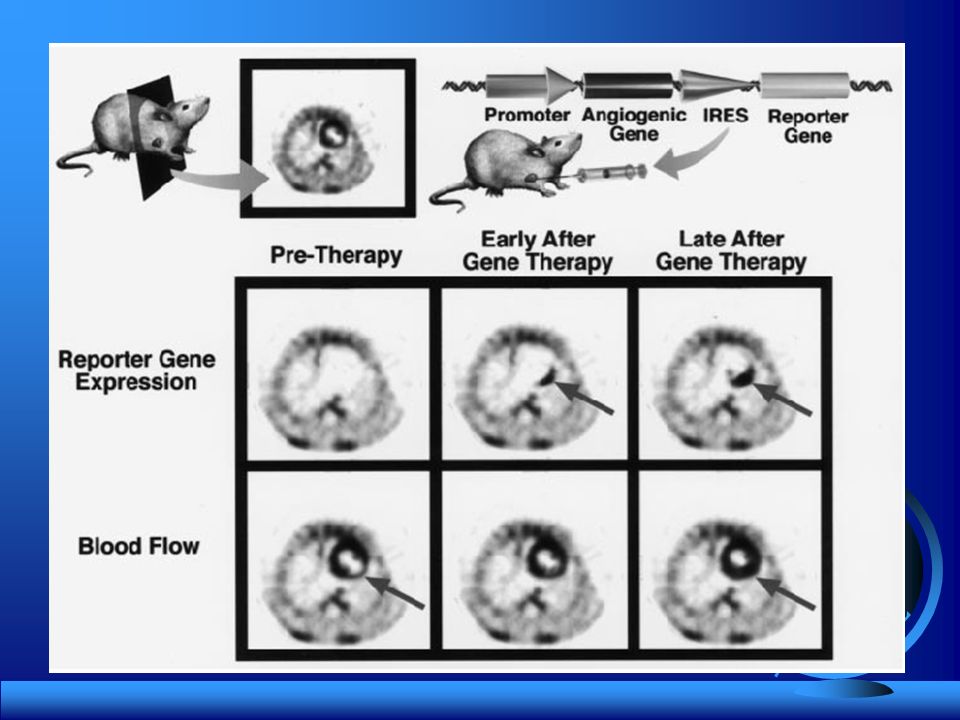
20
Whole body image of a normal rat injected with fluorine-18 fluorodeoxyglucose (FDG), illustrating glucose utilization. Mouse model with one tumor on each shoulder. The left tumor expresses the D2 receptor gene and uptakes FESP, while the tumor on the right, represses the tk gene and uptakes FPCV.

22
Human PET: 3-4mm; Target: 1-2mm Animal PET: 1-2 mm; Target: <0.5mm
024 Human PET: 3-4mm; Target: 1-2mm Animal PET: 1-2 mm; Target: <0.5mm

23
Simulations in PET Source Distributions Imaging Physics Attenuation Scattering etc.

24
045

25
The neue Cologne Phantom
3 mm structure 2 mm structure

26
Simulations in PET Imaging System Geometry Configurations

27
HRRT: Octagon - 120,000 crystals
936 electronic channels 4.486*109 LORs

28
A Benchtop Prototype for High-Throughput Animal Imaging
HRRT modules LSO crystals with DOI capability good spatial resolution ~2.42mm crystal pitch ~10mm DOI resolution good detection sensitivity high count rate large detection sensitive area ~25.2cm ×17.4cm 72×104 crystals per layer off-shelf, well tested, cost-effective design adjustable energy and coincidence windows We are setting up the proposed dual-panel system by using two HRRT modules from CPS. This module uses about 2.25mm wide LSO crystals and provides depth of interaction information by using two layers of LSO crystals of different decay time constants, each layer is 10 mm thick. The module can support high count rate. It has a large detection sensitive area, about 25.2x17.4cm and contains 104 by 72 crystals per layer. This module has been well tested and is available from CPS. It adopts quadrant sharing design to reduce the number of photomultiplier tubes to decrease the production cost.

29
Multi-Modality Integrative System Siemens “Molecular Imaging”
PET/SPECT PET/MRI PET/SPECT/CT For Animal Imaging Siemens “Molecular Imaging”

30
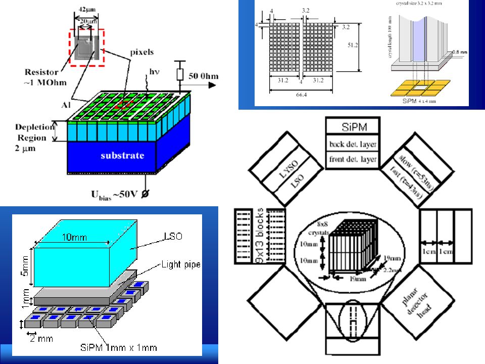
Scintillation Crystals
Simulations in PET Photon Detection Scintillation Crystals Photon Sensors PMT/APD/SiPM

31
Initial Photon Rate (ph/MeV-ns)
Scintillation properties of primary crystals in PET Material Denstiy (g/cm3) Decay time (ns) aLight Yield Initial Photon Rate (ph/MeV-ns) Energy resolution keV NaI:Tl 3.67 230 100 164 6.5 Bi4Ge3O12(BGO) 7.13 300 22 27 9.3 Gd2SiO5:Ce(GSO) 6.71 60 167 7.8 Y2SiO5:Ce(YSO) 4.54 70 377 9.0 Lu2SiO5:Ce(LSO) 7.40 40 80 750 7.9 cLu2(1-x)Y2xSiO5:Ce(LYSO) 7.11 845 7.5~9.5 dLu2(1-x)Gd2xSiO5:Ce(LGSO) 61 575 12.4 Lu2Si2O7:Ce(LPS) 6.23 38 692 9.5~12.5 BaF2 4.89 b0.8 b2300 7~8 LaBr3:Ce0.5% 5.29 35 162 1743 3.0 aRelative to NaI(Tl)=100 bIt is the fast scintillating component of BaF2. cx=0.1 dx=0.1
 Decay time. (ns) aLight. Yield. Initial Photon Rate (ph/MeV-ns) Energy resolution. keV. NaI:Tl Bi4Ge3O12(BGO) Gd2SiO5:Ce(GSO) Y2SiO5:Ce(YSO) Lu2SiO5:Ce(LSO) cLu2(1-x)Y2xSiO5:Ce(LYSO) ~9.5. dLu2(1-x)Gd2xSiO5:Ce(LGSO) Lu2Si2O7:Ce(LPS) ~12.5. BaF b0.8. b ~8. LaBr3:Ce0.5% aRelative to NaI(Tl)=100. bIt is the fast scintillating component of BaF2. cx=0.1. dx=0.1.")
32
PET Components detectors block detectors: BGO, LSO, GSO crystals

33
Quadrant Sharing Design
8x8 crystal matrix; two layer LSO LSO-fast/LSO-slow (or LSO/GSO) 128 single crystals in 2 layers 2.1 x 2.1 x 7.5 mm3
 128 single crystals in 2 layers 2.1 x 2.1 x 7.5 mm3.")
34
Simulations in PET Electronics (Fast Electronic)
")
35
Custom Integrated Circuit Electronics
Detector Analog ASIC Detector Digital ASIC Digital Coincidence ASIC Analog Detector Signals Processes Digital X, Y Energy, and Time Data Processes Digital Crystal Position and Time Data Processes Digital PET Coincidence Data

36
CMOS PET Front End Integrated Circuit
Serial Interface Gain Control DACs CMOS PET Front End Integrated Circuit Preamps, Variable Constant Fraction Gain Amps, Summers Discriminator* ECL Driver 6.4 mm Gated Integrators CFD Thld DAC X, Y Offset DACs 6.0 mm * U.S. Patent 5,396,187

37
Depth-of-Interaction (DOI)
Simulations in PET List Mode Position Energy Timing Depth-of-Interaction (DOI) Time-of-Flight (TOF)
 Time-of-Flight (TOF)")
38
DOI Detectors Phoswich detectors photo-diodes LSO GSO/LSO PMT
scintillator (BGO) PMT photo diode
 PMT. photo diode.")
39
Depth-of-Interaction (DOI) Detector
 Detector")
40
Time-of-Flight Tomograph
x Can localize source along line of flight - depends on timing resolution of detectors Time of flight information can improve signal-to-noise in images - weighted back-projection along line-of-response (LOR) D One normal variation in PET cameras is the “time-of-flight” or TOF design. By measuring the difference in arrival time at the two detectors, the positron source can be localized along the line of flight. Doing this does not improve the spatial resolution, but improves the signal to noise ratio (the mechanism will be described in more detail in the next slide) — the variance improves by a factor of 2D/ct, where D is the diameter of the radionuclide distribution, c is the speed of light, and t is the TOF resolution. Several TOF PET systems were built in the 1980’s with barium fluoride or cesium fluoride scintillators. They achieved ~500 ps timing resolution, which results in 8 cm localization. For objects the size of the human head (which was what most PET cameras imaged in the 1980’s) the net result is a tomograph with a factor of ~2 lower variance than a non-TOF BGO tomograph. Problems arose from the use of barium fluoride as a scintillator. It is less dense than BGO, and so the spatial resolution is degraded. In addition, the wavelength of its fast emission is in the hard UV, which made it difficult to work with (i.e. expensive) because it does not penetrate glass-windowed photomultiplier tubes or any known glue (to couple the crystal to the photomultiplier tube). Finally, it was difficult to keep these cameras in tune. Thus, TOF PET largely died at the end of the 80’s. However, the advent of LSO and other new PET scintillators (that can provide excellent timing resolution without the material drawbacks of barium fluoride) makes TOF a promising direction for modern PET. x = uncertainty in position along LOR = c . t/2 Karp, et al, UPenn
 D. One normal variation in PET cameras is the time-of-flight or TOF design. By measuring the difference in arrival time at the two detectors, the positron source can be localized along the line of flight. Doing this does not improve the spatial resolution, but improves the signal to noise ratio (the mechanism will be described in more detail in the next slide) — the variance improves by a factor of 2D/ct, where D is the diameter of the radionuclide distribution, c is the speed of light, and t is the TOF resolution. Several TOF PET systems were built in the 1980’s with barium fluoride or cesium fluoride scintillators. They achieved ~500 ps timing resolution, which results in 8 cm localization. For objects the size of the human head (which was what most PET cameras imaged in the 1980’s) the net result is a tomograph with a factor of ~2 lower variance than a non-TOF BGO tomograph. Problems arose from the use of barium fluoride as a scintillator. It is less dense than BGO, and so the spatial resolution is degraded. In addition, the wavelength of its fast emission is in the hard UV, which made it difficult to work with (i.e. expensive) because it does not penetrate glass-windowed photomultiplier tubes or any known glue (to couple the crystal to the photomultiplier tube). Finally, it was difficult to keep these cameras in tune. Thus, TOF PET largely died at the end of the 80’s. However, the advent of LSO and other new PET scintillators (that can provide excellent timing resolution without the material drawbacks of barium fluoride) makes TOF a promising direction for modern PET. x = uncertainty in position along LOR. = c . t/2. Karp, et al, UPenn.")
41
Benefit of TOF no TOF 300 ps TOF 1 Mcts 5 Mcts 10 Mcts
Better image quality Faster scan time 1 Mcts 5Mcts 1Mcts 1Mcts TOF 5Mcts TOF 5 Mcts 10 Mcts Karp, et al, UPenn

42
Simulations in PET Image Reconstruction Image Processing Image Analysis

43
Multi-Modality Bayesian Image Reconstruction
One area that our image reconstruction group pioneered is the concept of multi-modality image reconstruction. Using the co-registered CT or MRI images, Dr. Chen and his group demonstrated that image quality can be improved very substantially by a Bayesian image reconstruction algorithm that incorporates high-resolution information from CT/MRI in the reconstruction of PET or SPECT images. Upper Two: Filtered BackProj. Lower Two: Multi-Modality Image Reconstru. Chen, Kao, et al Co-registration of PET/SPECT with CT/MRI Incorporation of high-resolution information from the co- registered CT/MR images into a Bayesian image recons- truction framework to enhance image quality of PET/SPECT Using the co-registered CT/MR images as an anatomic map in correction for attenuation and scatters in PET or SPECT

44
Dual Planar Detector High-Throughput Animal PET Imager Dual Layer D.O.I. Detectors (LSO) Variable Detector Face-to-Face Spacing

45
Example Reconstruction
25.2 cm 5 cm ~16 cm Noiseless data To examine how the missing data affect image quality, we do a preliminary study by considering only the stationary configuration with different number of subjects inside. The objects are the these 2cm-diameter disks. Again, the panel spacing is 5 cm. We use computer simulations to generate data and perform reconstruction by using the EM algorithm. The results shown here that you can get decent reconstruction up to about ~16 cm wide FOV, especially for noisy data no noticeable differences are observed between 5-subject and one-subject imaging. So our results suggest that with a compact geometry and good reconstruction algorithm we can indeed achieve good reconstruction for a large FOV. Noisy data

46
Simulations in PET Physiology Biochemistry Biology

47
18Fluoro-2-deoxy-D-glucose

48
024

49
System Geometry/Configuration Source Distribution/Physics
Simulations in PET System Geometry/Configuration Source Distribution/Physics Photon Detection/Collection Electronic ListMode/DOI/TOF Image Reconstruction Physiological Modeling

Similar presentations


 Assen S. Kirov Department of Medical Physics Memorial.>")


