Download presentation
Presentation is loading. Please wait.

1
Developing a low cost dish for MeerKAT Willem Esterhuyse Subsystem manager: Antenna Structures willem@ska.ac.za 083 447 1615

2
Overview Introduction Partners Main Specs Philosophy Schedule Progress Analyses (CFD/FEA) Detail Design Manufacturing/Construction Acceptance/Verification Life after XDM (Cost optimization and KAT7 – composite dish) Conclusion
 Detail Design Manufacturing/Construction Acceptance/Verification Life after XDM (Cost optimization and KAT7 – composite dish) Conclusion")
3
Introduction (1) KAT Project Phases XDMKAT7MeerKAT Antenna structures open tender. Equatorial mount still considered – many suppliers not interested. Antennas open tender – proposal deadline 31 March. Costs sensitive at this stage Antennas open tender?? This presentation from mechanical design perspective Antenna performance/Feeds – EMSS (LJ du Toit/ Isak Theron)
.")
4
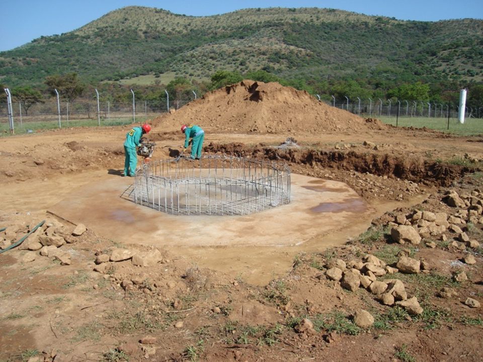
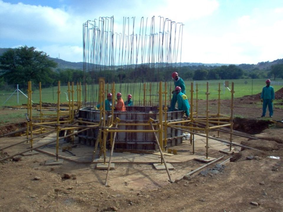
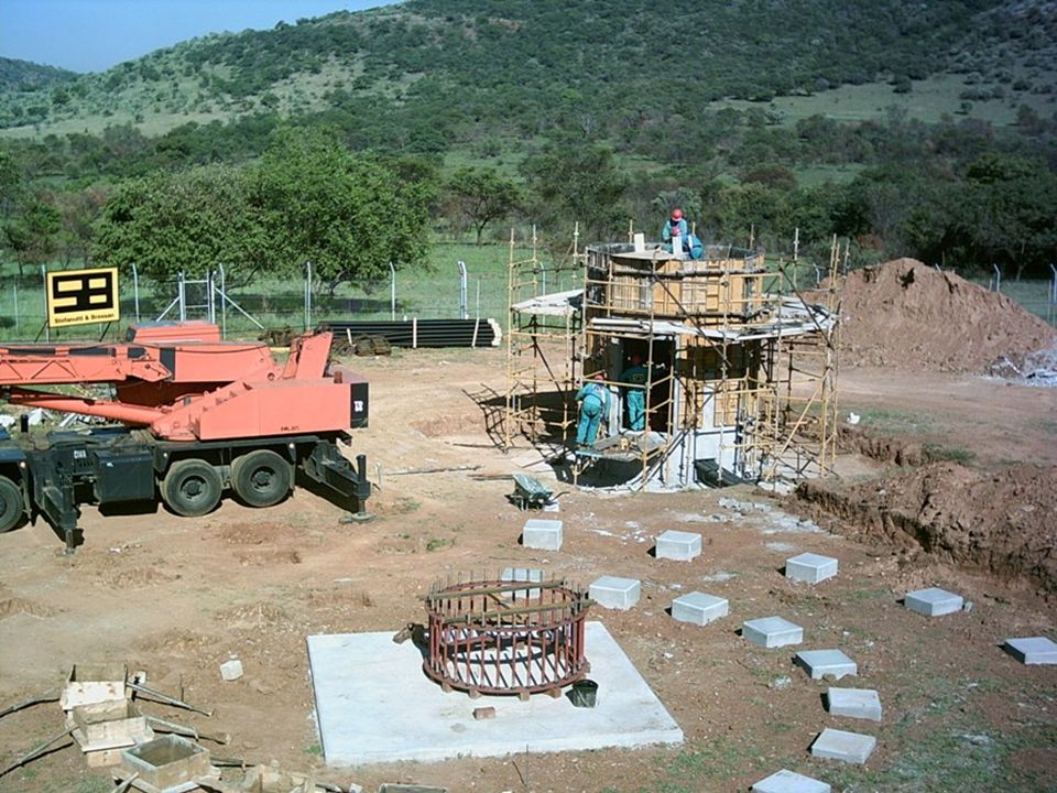
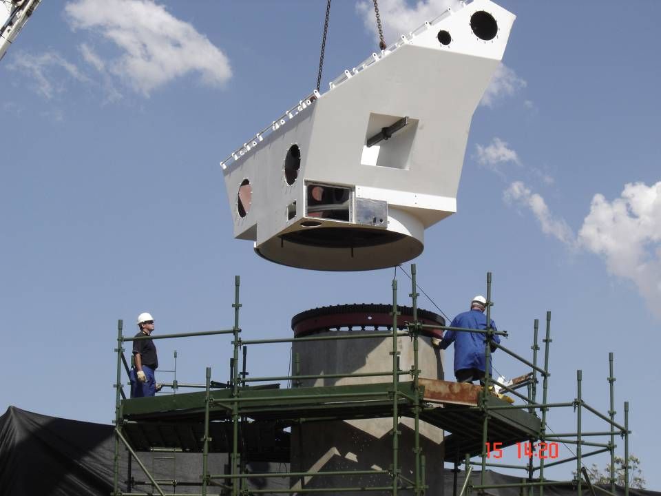
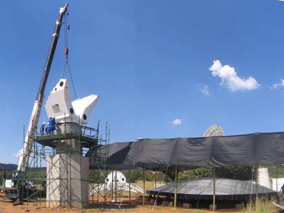
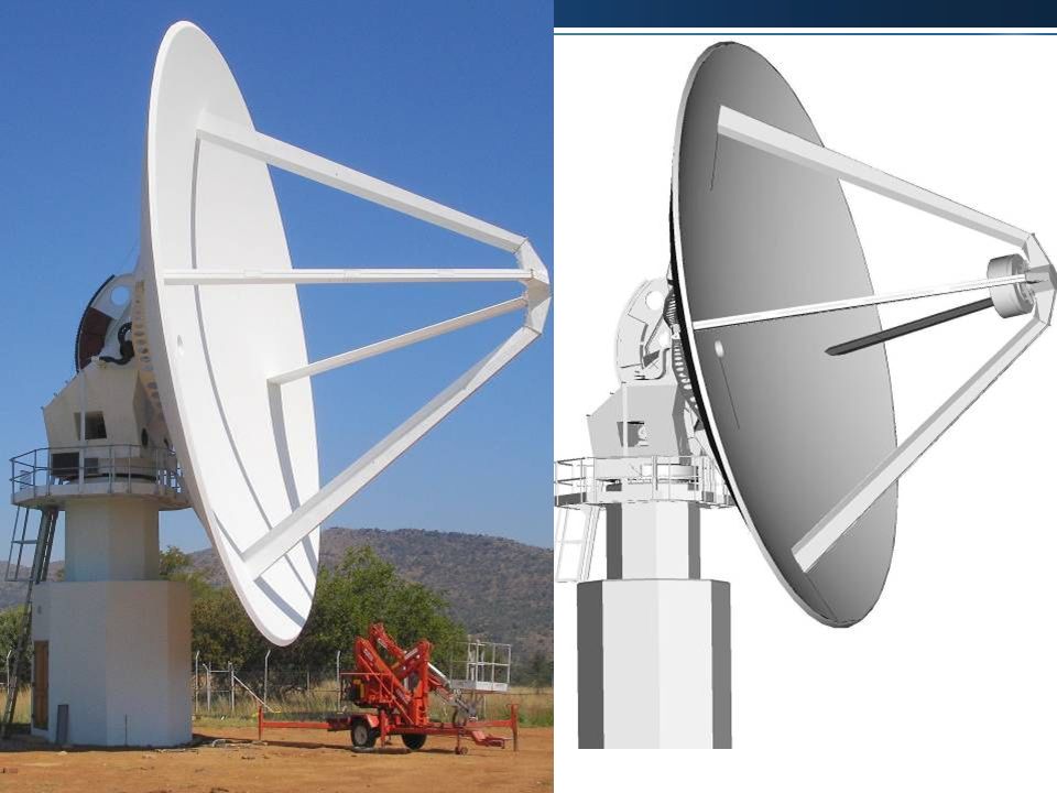
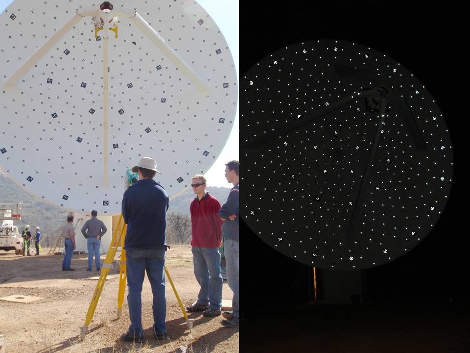
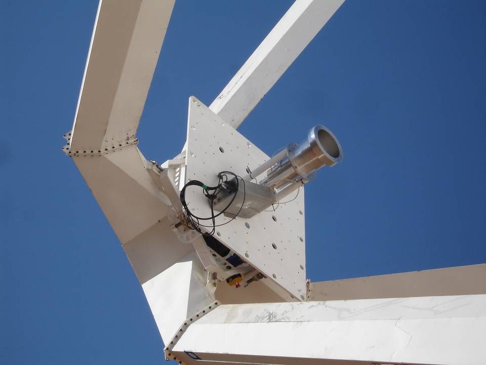
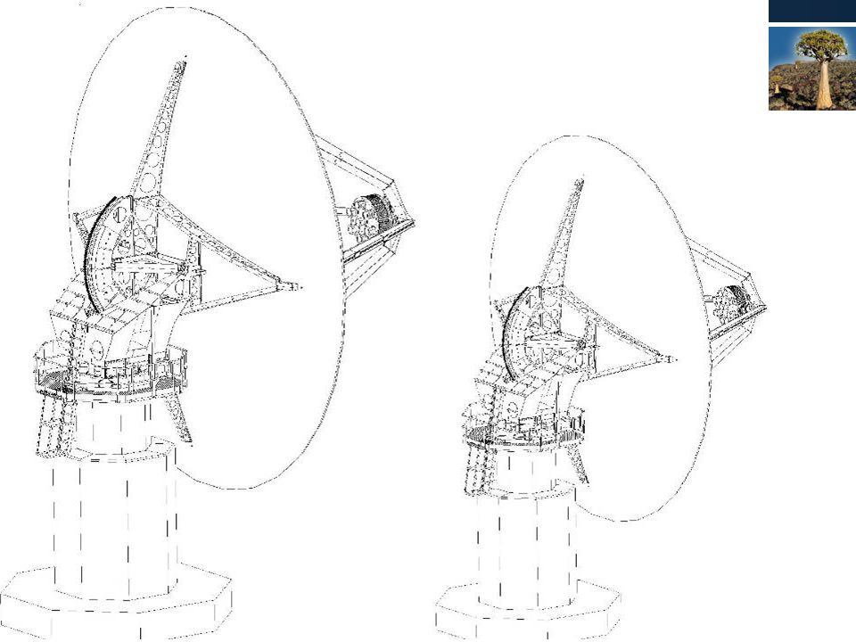
Introduction (2) - XDM 15 meter PF antenna on ALT-AZ mount with feed rotator One-piece composite reflector that is structural Simple back-up structure No Panels to align Weight saving Concrete pedestal Pedestal only 30% of foundation (bedrock) volume Aim – Antenna for KAT that is relevant to SKA. Technical/Cost Development Subcontracted (time constraints) IST Dynamics (PTY) LTD Single line of responsibility (time, risk) MMS subcontracted for dish
 IST Dynamics (PTY) LTD Single line of responsibility (time, risk) MMS subcontracted for dish.")
5
Partners - IST IST Dynamics Prime contractor – IST exists for more than 25 years High tech electro-mechanical systems + software Military is biggest client ISO 9001 and ISO 14001 www.ist.co.za, follow link to dynamics Prototype development subcontracted to IST Dynamics. Shared IP.

6
Partners - MMS MMS Subcontracted by IST Dish construction and design Exceptional experience in Composite design and manufacture Existing for more than 20 years For more detail, see www.mmstechno.co.za

7
Main Specifications and Design Goal XDM KAT7/MeerKAT Provisional SpecDesign Goal Pointing Accuracy (deg)0.040.0225 arcsec RMS Surface Accuracy (mm rms)41.52 (target 1)mm Frequency Range (MHz)700 - 1700Up to 8 GHz Wind (Operational) km/h2036 Wind (Marginal Operation) km/h3645 Wind (Drive to Stow) km/h3655 Wind (Survival) km/h160 Azimuth Rotation speed (deg/s)122 Elevation speed (deg/s)0.511 Diameter15 12 F/D0.5 0.38 Lowest Natural Frequency (Hz)33+ Feed Mass (kg)200 Single pixel Mount Type All-Az with Rotator, but equatorial considered.Alt-Az
 arcsec RMS Surface Accuracy (mm rms)41.52 (target 1)mm Frequency Range (MHz) Up to 8 GHz Wind (Operational) km/h2036 Wind (Marginal Operation) km/h3645 Wind (Drive to Stow) km/h3655 Wind (Survival) km/h160 Azimuth Rotation speed (deg/s)122 Elevation speed (deg/s)0.511 Diameter15 12 F/D Lowest Natural Frequency (Hz)33+ Feed Mass (kg)200 Single pixel Mount Type All-Az with Rotator, but equatorial considered.Alt-Az")
8
Philosophy Highest risk (technical and cost) – Reflector Preferably one-piece reflector (no alignment of panels) This requires manufacturing on site Tooling costs very high for steel, much lower for composites Composites attractive for smaller quantities (limited budget) Composites offer other advantages as well Lighter for same stiffness/strenght On site manufacturing easy (minimal equipment required) Better thermal performance Going to offset antennas not significant impact on reflector Preferably very simple backup structure (if any) – structural reflector Pedestal – concrete (30% of foundation concrete) Revisited in cost optimization study
 – Reflector Preferably one-piece reflector (no alignment of panels) This requires manufacturing on site Tooling costs very high for steel, much lower for composites Composites attractive for smaller quantities (limited budget) Composites offer other advantages as well Lighter for same stiffness/strenght On site manufacturing easy (minimal equipment required) Better thermal performance Going to offset antennas not significant impact on reflector Preferably very simple backup structure (if any) – structural reflector Pedestal – concrete (30% of foundation concrete) Revisited in cost optimization study")
9
Schedule (KAT Antenna Structures) XDM Contract Signed 24 April 06(DONE) PDR 20 June 06(DONE) CDR 28 Aug 06(DONE) FATS12 Feb 07(DONE) Installation Completed 16 May 07(DONE) ATP Completed17 July 07(DONE) Documentation Completed 17 July 07(DONE) KAT7 & MeerKAT 12m Design/Cost optimizationSept 07 – Dec07(DONE) KAT7 TenderJan 07(Progress) KAT7 Contract award April 07 KAT7 Array CompletedNov 09 MeerKAT Contract award Jan 2010 MeerKAT Array CompletedNov 2012
 XDM Contract Signed 24 April 06(DONE) PDR 20 June 06(DONE) CDR 28 Aug 06(DONE) FATS12 Feb 07(DONE) Installation Completed 16 May 07(DONE) ATP Completed17 July 07(DONE) Documentation Completed 17 July 07(DONE) KAT7 & MeerKAT 12m Design/Cost optimizationSept 07 – Dec07(DONE) KAT7 TenderJan 07(Progress) KAT7 Contract award April 07 KAT7 Array CompletedNov 09 MeerKAT Contract award Jan 2010 MeerKAT Array CompletedNov 2012")
10
ANALYSES - CFD Detailed CFD (Computational Fluid Dynamics) analyses to determine pressures on dish as result of wind loading (for use in FEA analyses) Results compared to published results – good correlation Results compared with limited experimental data – good correlation
 analyses to determine pressures on dish as result of wind loading (for use in FEA analyses) Results compared to published results – good correlation Results compared with limited experimental data – good correlation")
11
Analyses – FEA – Modes Mode 1: 4.2 Hz side to side Mode 2: 4.4 Hz dish “flaps” Mode 3: 4.7 Hz nodding

12
Analyses – FEA - displacements LC Dish RMS error to focus [mm] Actual focus point movement relative to best fit parabola focus point Ux [mm] Focus Uy [mm] In-plane Uz [mm] In-plane 10.437-4.390-4.33 20.147+3.430+0.16 30.165-0.3-0.160 40.229+3.54+0.17+0.05 50.334+6.620+1.55 60.416-4.730-1.94 70.464+15.9400 80.685+19.720+1.54 90.616-8.300+3.11 100.983+5.180+2.07 110.447-5.680-6.09
![Analyses – FEA - displacements LC Dish RMS error to focus [mm] Actual focus point movement relative to best fit parabola focus point Ux [mm] Focus Uy [mm] In-plane Uz [mm] In-plane](http://images.slideplayer.com/24/7264107/slides/slide_12.jpg "Analyses – FEA - displacements LC Dish RMS error to focus [mm] Actual focus point movement relative to best fit parabola focus point Ux [mm] Focus Uy [mm] In-plane Uz [mm] In-plane")
13
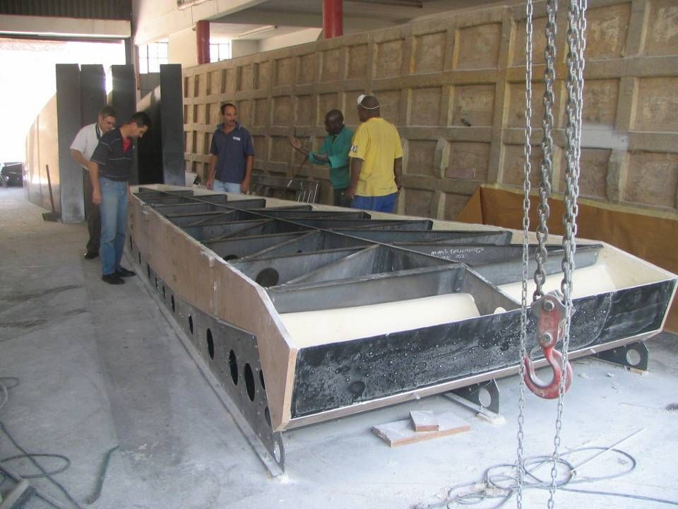
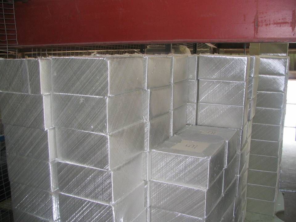
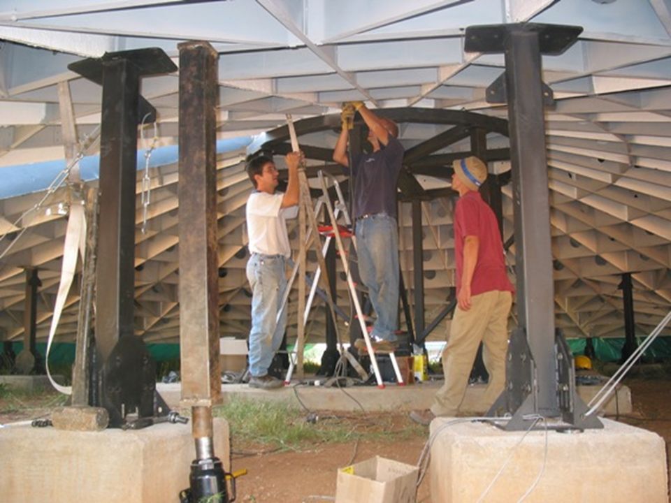
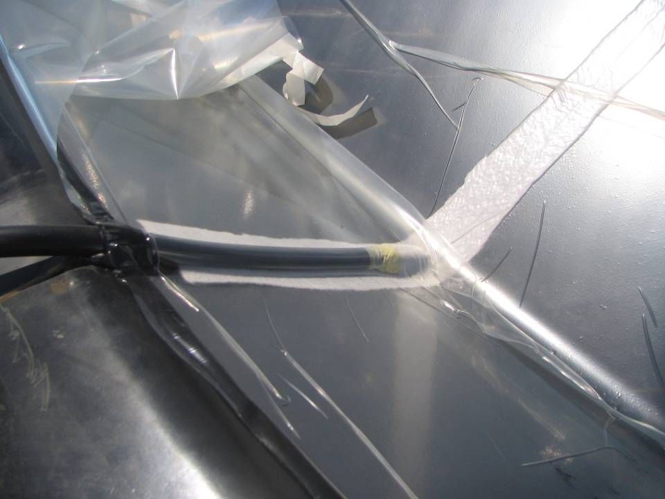
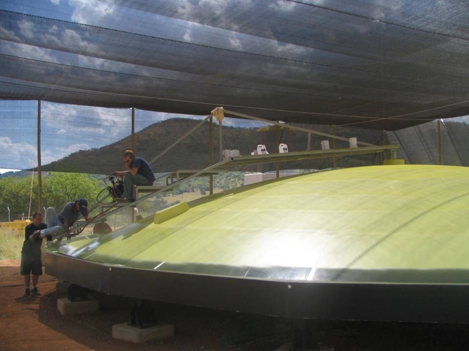
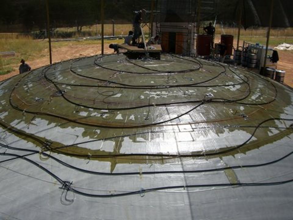
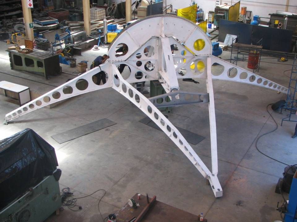
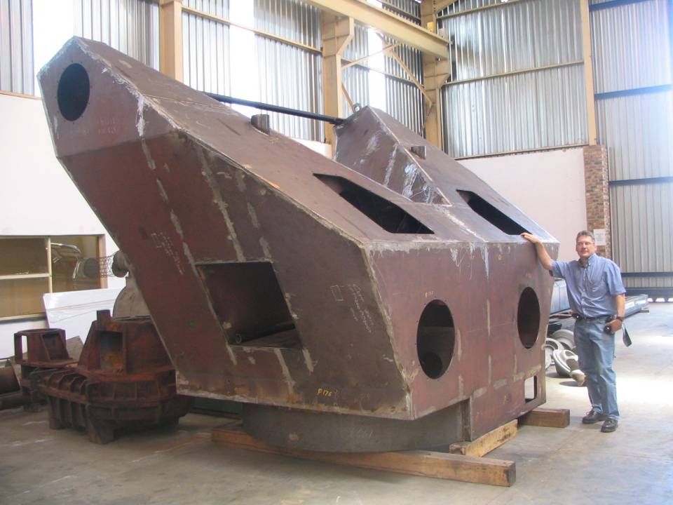
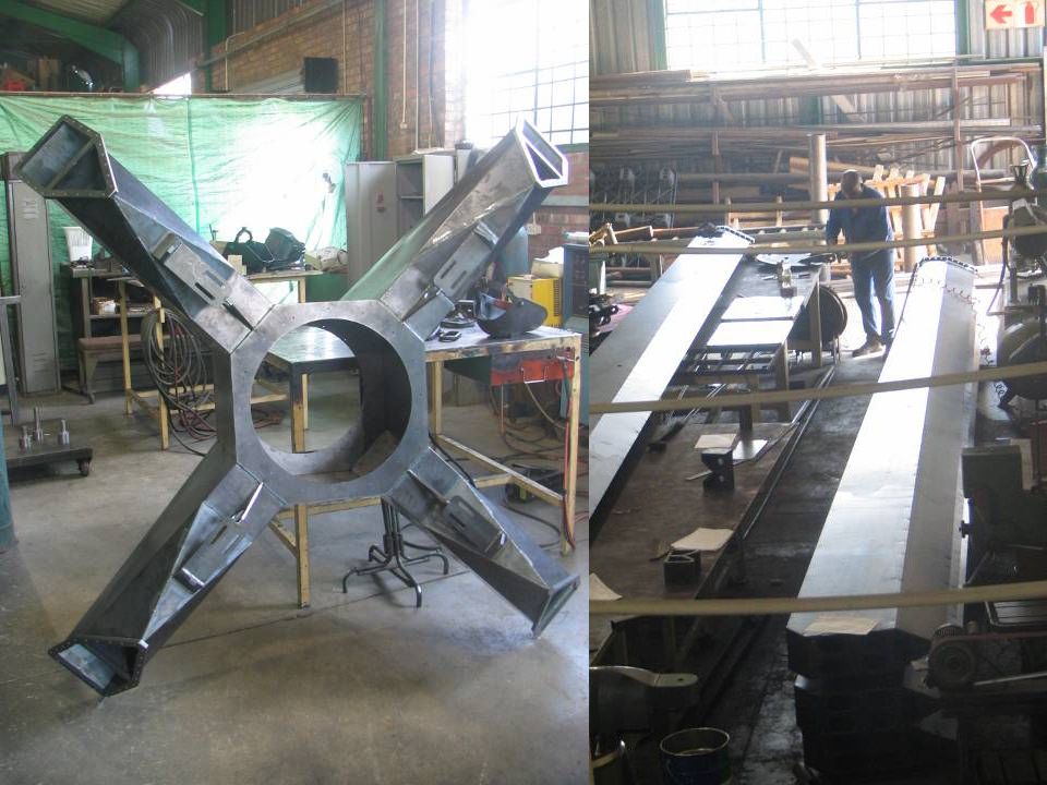
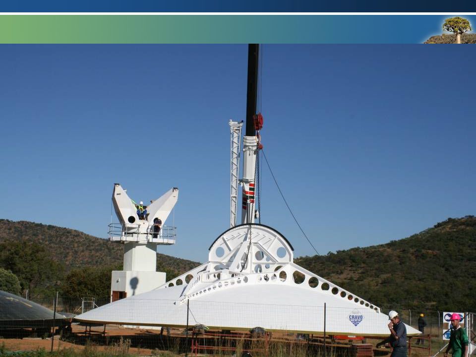
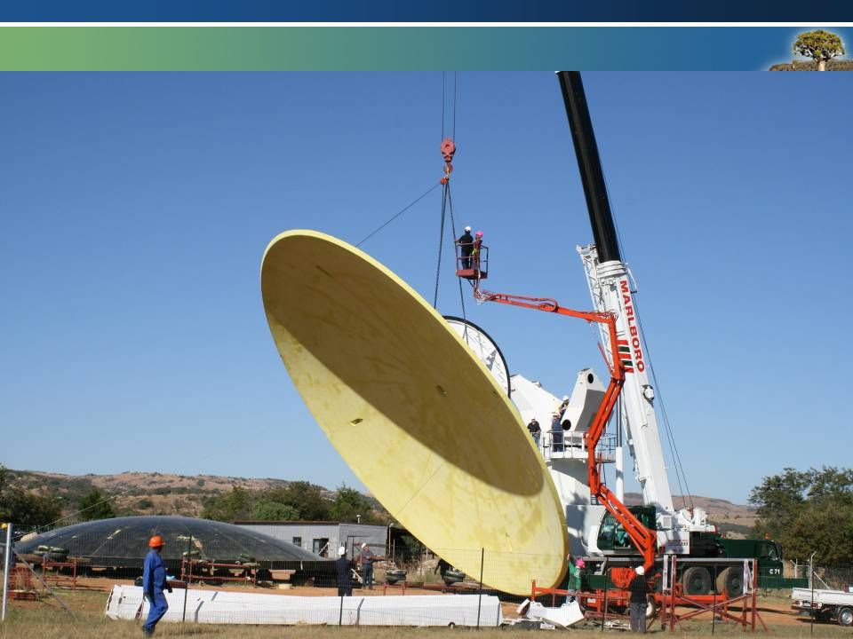
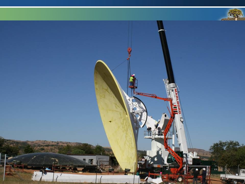
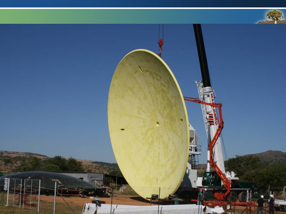
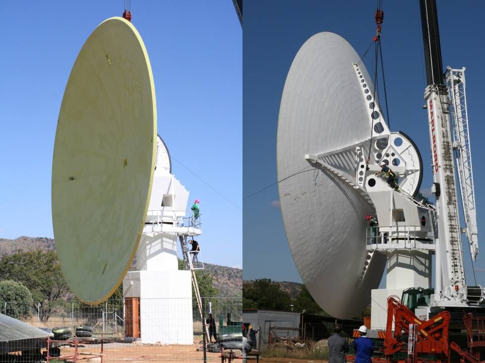
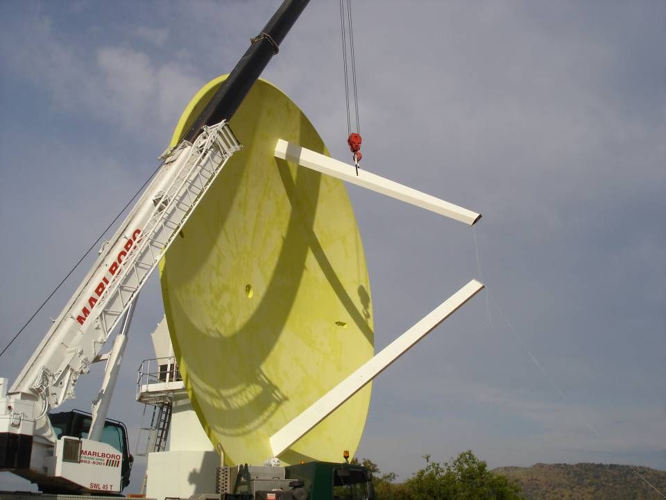
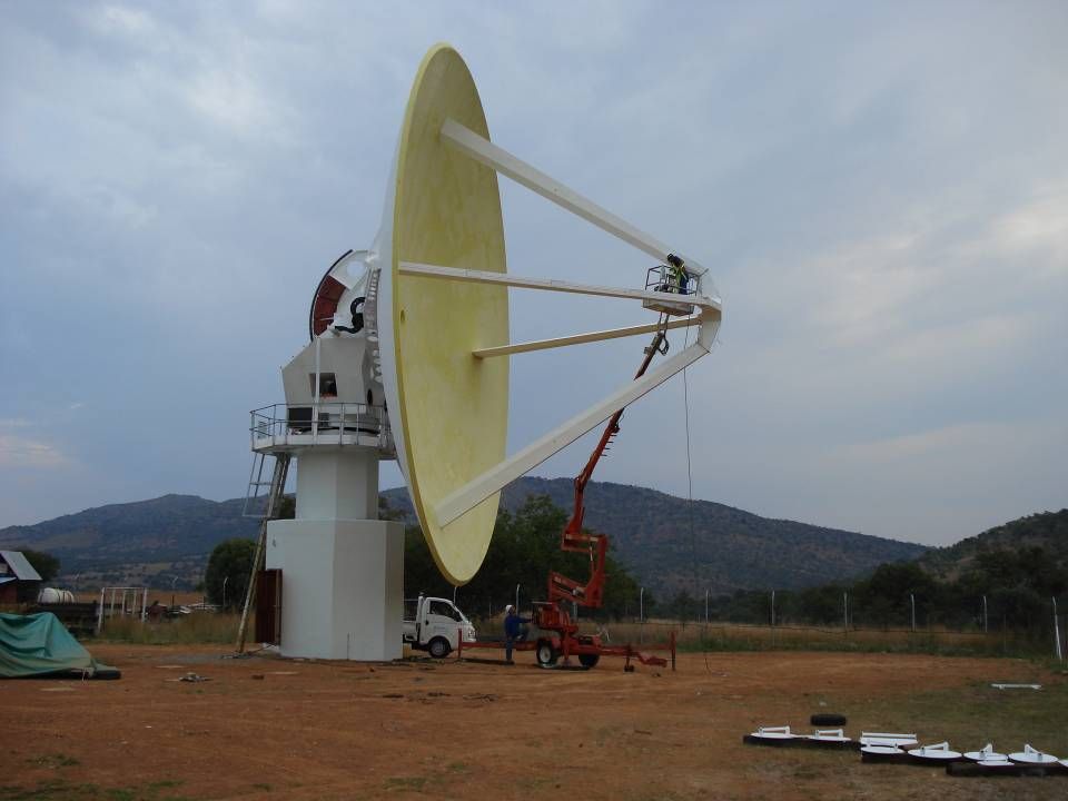
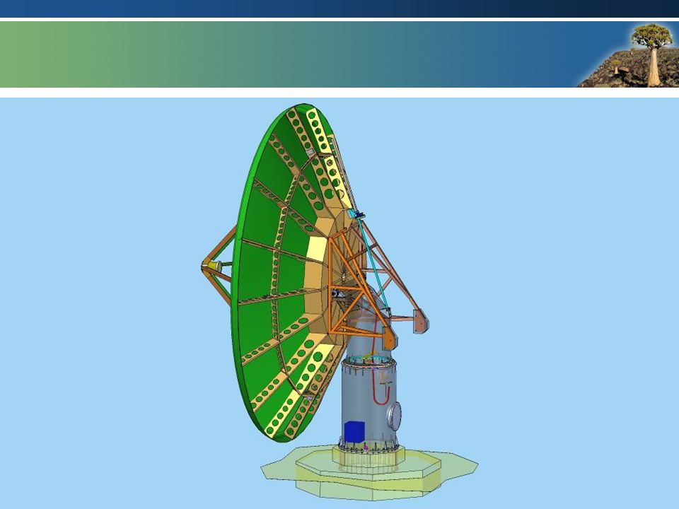
Detail Design/Manufacture - Dish Very simple backup structure Dish is structural (approx. 5 Tons) Symmetric, to eliminate curing distortions Manufacturing (see pictures later): Machine patterns (composite pattern material) Make composite moulds of the patterns Combine composite moulds to create dish mould Innovative and cheap honeycomb structure (off the shelf honeycomb cores very expensive). Vacuum Infusion process used for molding entire dish as a unit
 Symmetric, to eliminate curing distortions Manufacturing (see pictures later): Machine patterns (composite pattern material) Make composite moulds of the patterns Combine composite moulds to create dish mould Innovative and cheap honeycomb structure (off the shelf honeycomb cores very expensive). Vacuum Infusion process used for molding entire dish as a unit.")
14
Detail Design/Manufacture - Dish Layer noMaterial Thickness [mm] 1 Paint 0.05 – 0.1 2 Reflective aluminium layer 0.1 – 0.2 3 Gelcoat layer/FSP layer 0.5 4 E-glass vinylester 6 5 Quasi honeycomb structure 150 6 E-glass vinylester 6 7 Flowcoat layer/FSP layer 0.5 Typical dish lay-up
![Detail Design/Manufacture - Dish Layer noMaterial Thickness [mm] 1 Paint 0.05 – Reflective aluminium layer 0.1 – Gelcoat layer/FSP layer E-glass vinylester 6 5 Quasi honeycomb structure E-glass vinylester 6 7 Flowcoat layer/FSP layer 0.5 Typical dish lay-up](http://images.slideplayer.com/24/7264107/slides/slide_14.jpg "Detail Design/Manufacture - Dish Layer noMaterial Thickness [mm] 1 Paint 0.05 – Reflective aluminium layer 0.1 – Gelcoat layer/FSP layer E-glass vinylester 6 5 Quasi honeycomb structure E-glass vinylester 6 7 Flowcoat layer/FSP layer 0.5 Typical dish lay-up")
15
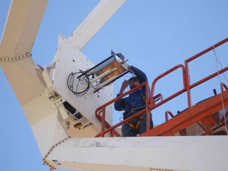
Detail Design – Drives/Controls Azimuth axis 1 spring - loaded drive 2 deg/s, 460 degree travel Elevation axis 1 spring - loaded drive 1 deg/s, 0 to 95 degree elevation range Elevation axis is BALANCED Light dish (composites) makes this possible with minimal use of counter weights Feed rotator axis 380 degree travel
 makes this possible with minimal use of counter weights Feed rotator axis 380 degree travel")
16
Typical Up/Down, Left/Right, CW/CCW Emergency stop (for all drives) Elevation Stow Manual Control / Normal Control / Off Functions in absence of control computer Commissioning/Maintenance No feedback control on position All limits active Drives/Controls – Manual Control
 Elevation Stow Manual Control / Normal Control / Off Functions in absence of control computer Commissioning/Maintenance No feedback control on position All limits active Drives/Controls – Manual Control")
50
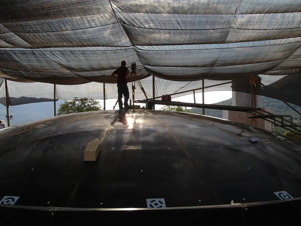
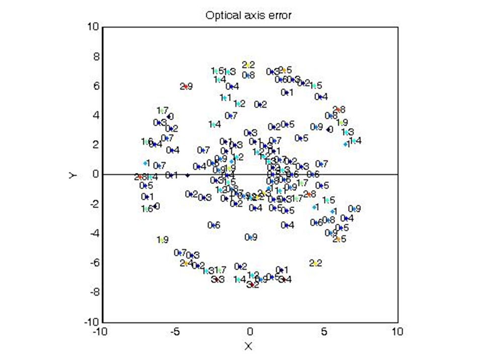
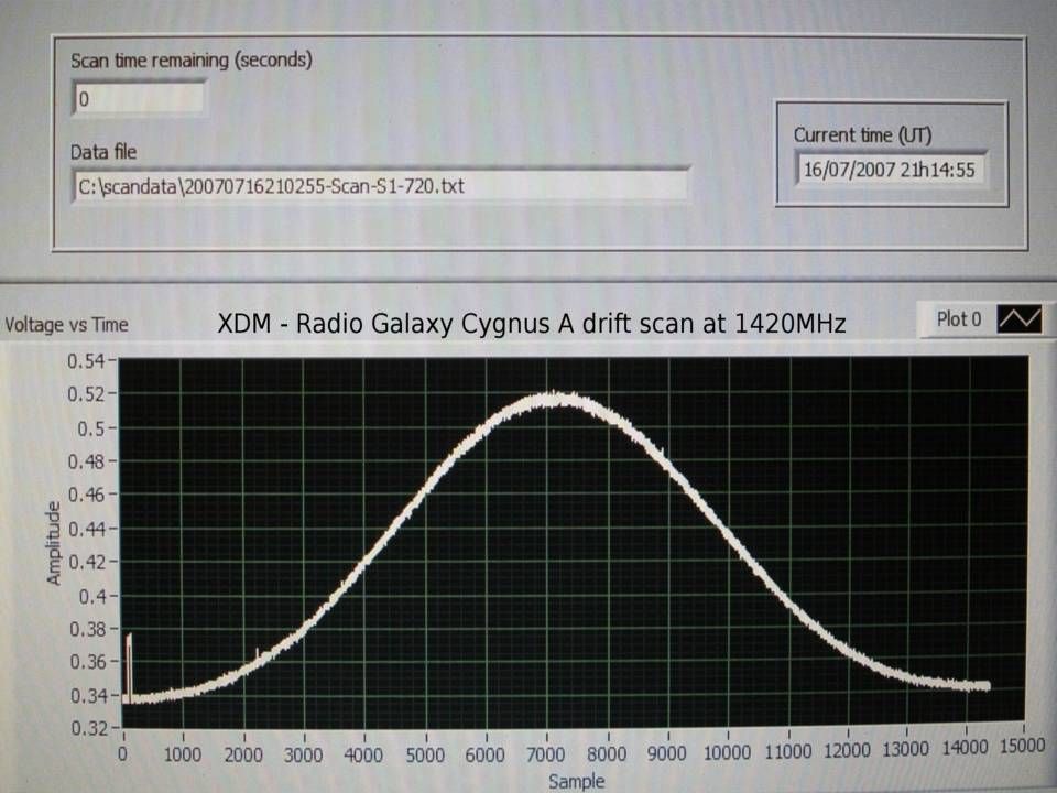
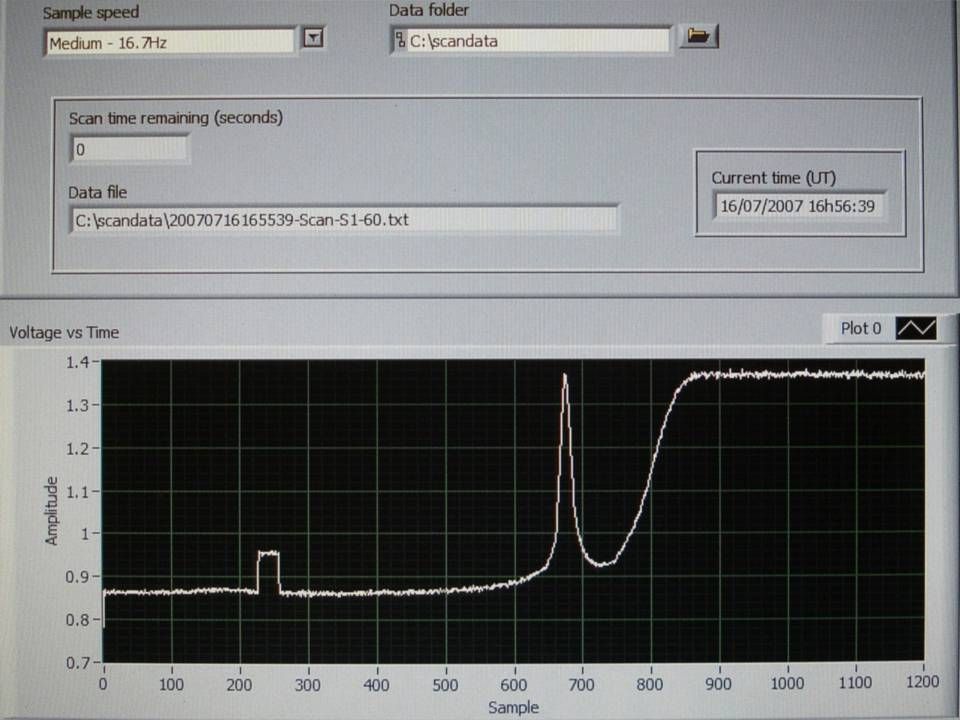
Verification/Acceptance Completed Achieved all design goals Dish tested at 1.42 and 12 GHz Dish accuracy around 1.7mm RMS (Confirmed with Theodolite and Photogrammetry measurements) Improve? – pattern from Al, mold. Al Flame sprayed surface works well Pointing – 25 arcsec RMS (optically) Improve? – probably 2 drives Thermal performance – thermocouples molded into dish front and rear to verify analyses assumptions.
 Improve. – probably 2 drives Thermal performance – thermocouples molded into dish front and rear to verify analyses assumptions..")
59
Life after XDM - Dishes Optimization and redesign (12m dish) effort completed. Feb 08 – tender out for KAT7 Apr 08 – KAT7 tender award Open tender, ie composite dish one of options Dec 09 - KAT7 completion KAT7 prototype for MeerKAT Aggressive timescales

62
Gravity

63
Wind from front

64
Temperature, -5ºC from 20ºC

65
Gravity + Wind from side + Temperature, +40ºC, dish front +60ºC, from 20ºC

66
Gravity

67
Wind from side

68
Gravity + Temperature, +40ºC, dish front +60ºC, from 20ºC

69
Frequencies Mode 1: 4.58 Hz

70
Frequencies Mode 1: 4.51 Hz

71
Conclusion XDM Well engineered dish – not optimized for low frequencies Believe we have made good progress in developing a fairly innovative dish in a short period of time from zero experience Major specifications were met Dish can be manufactured on site with little infrastructure requirement Cost optimization on 12m dish completed by IST Tender for KAT7 currently open (closes 31 March) Cost sensitive at this stage Composite dish competes on cost MeerKAT choice of dish not decided yet. Final word – SKA Cost targets (risks, approach, site work)
.")
Similar presentations


, Vice Director @JLART Joint Lab. for Radio.>")


 GG Phase A-2 Study funded by ASI ongoing at TAS-I (TO) with support from GG/GGG scientists GG target: test the Equivalence Principle.>")


