Download presentation
Presentation is loading. Please wait.

1
University of Chemical Technology and Metallurgy Department of Material Science and Engineering FINITEELEMENT METHOD By eng. Veselin Paunov Prof. Veselin Iliev

2
Table of content Revile of the problem Revile of the problem Creation of geometry Creation of geometry Procedure of solution Procedure of solution Results Results Answer of questions Answer of questions

3
Revile of the problem

4
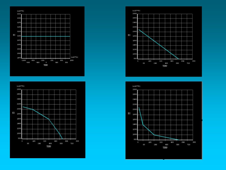
Assignment: The beam with dimensions 140x20x50 cm is fixed and loaded as is shown in firg.1. The beam is isolated at boundaries and exchange heat at contacts with supported plates. The beam material is homogeneous linear elastic with Poisson’s ratio ν=0.27 and temperature-dependant module of elasticity (fig. 2). Determine the stress and strain state in varies temperature-elasticity dependences. Assignment: The beam with dimensions 140x20x50 cm is fixed and loaded as is shown in firg.1. The beam is isolated at boundaries and exchange heat at contacts with supported plates. The beam material is homogeneous linear elastic with Poisson’s ratio ν=0.27 and temperature-dependant module of elasticity (fig. 2). Determine the stress and strain state in varies temperature-elasticity dependences. Submit: Submit: 1. Geometrical model, including the mesh and the boundary conditions. 1. Geometrical model, including the mesh and the boundary conditions. 2. The stress (von Mises) state for Material 2. 2. The stress (von Mises) state for Material 2. 3. The strain state for Material 3. 3. The strain state for Material 3. 4. Compare the flexure of the beam for the materials in fig. 2. 4. Compare the flexure of the beam for the materials in fig. 2. Answer the next questions: Answer the next questions: 1. What is the mechanical behavior peculiarity of the material and where it is treated in the solution? 1. What is the mechanical behavior peculiarity of the material and where it is treated in the solution? 2. What element type was used? 2. What element type was used? 3. What element options were used? 3. What element options were used? 4. What real constants were used? 4. What real constants were used? 5. How many nodes and elements were created? 5. How many nodes and elements were created? 6. What is the % error for your solution? 6. What is the % error for your solution?
. Determine the stress and strain state in varies temperature-elasticity dependences. Assignment: The beam with dimensions 140x20x50 cm is fixed and loaded as is shown in firg.1. The beam is isolated at boundaries and exchange heat at contacts with supported plates. The beam material is homogeneous linear elastic with Poisson’s ratio ν=0.27 and temperature-dependant module of elasticity (fig. 2). Determine the stress and strain state in varies temperature-elasticity dependences. Submit: Submit: 1. Geometrical model, including the mesh and the boundary conditions. 1. Geometrical model, including the mesh and the boundary conditions. 2. The stress (von Mises) state for Material The stress (von Mises) state for Material The strain state for Material The strain state for Material Compare the flexure of the beam for the materials in fig Compare the flexure of the beam for the materials in fig. 2. Answer the next questions: Answer the next questions: 1. What is the mechanical behavior peculiarity of the material and where it is treated in the solution. 1. What is the mechanical behavior peculiarity of the material and where it is treated in the solution. 2. What element type was used. 2. What element type was used. 3. What element options were used. 3. What element options were used. 4. What real constants were used. 4. What real constants were used. 5. How many nodes and elements were created. 5. How many nodes and elements were created. 6. What is the % error for your solution. 6. What is the % error for your solution .")
6
Setting the preference Setting the preference Setting temperature units Setting temperature units Setting the element Setting the element Creation of geometry Creation of geometry Setting material properties Setting material properties Creation of the geometry

9
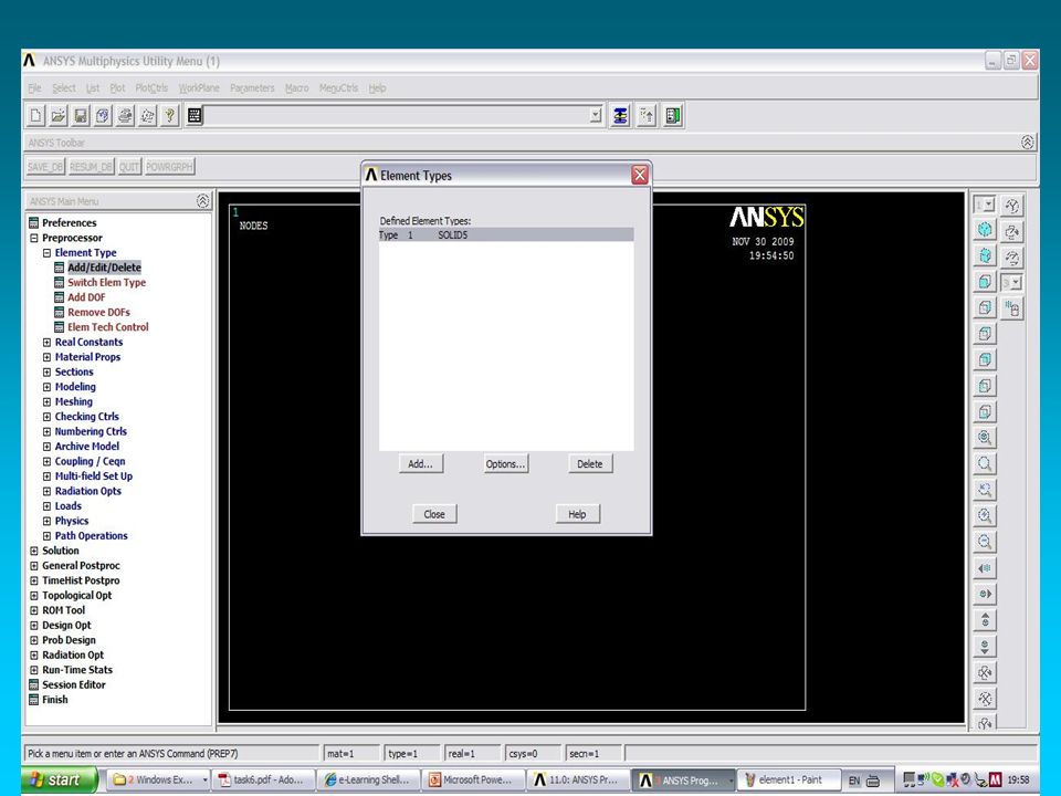
The used element is solid 5.

11
Geometry creation.

12
Setting material properties for every material. For the task we have to apply thermal conductivity, Poisson's ratio v=0.27 and temperature- dependant module of elasticity. Material 1

13
Material 2

14
Meshing of the model

15
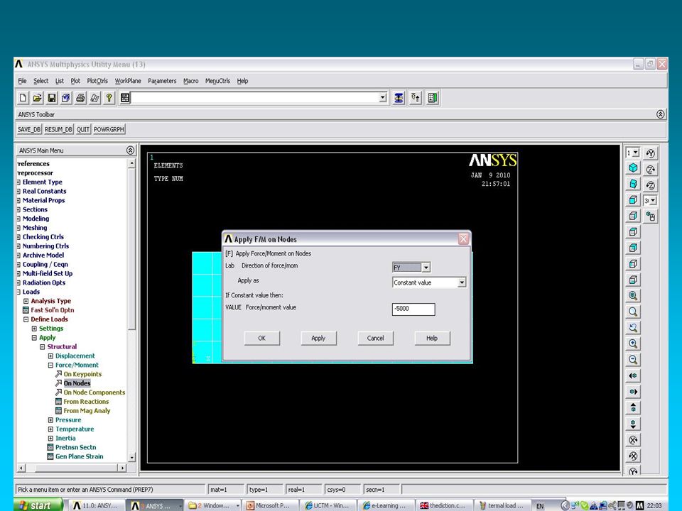
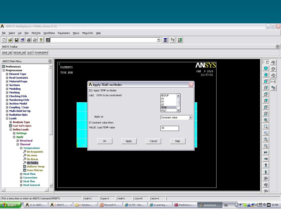
Appling the loads

19
Solving of the problem material 1

20
Material 2

21
Material 3

22
Material 4

23
von Mises state for material 2

24
Total thermal strain state for material 3

25
Material 1

26
Material 2

27
Material 3

28
Material 4

29
Answers of the questions 1. What is the mechanical behavior peculiarity of the material and where it is treated in the solution? 2. What element type was used? 3. What element options were used? 4. What real constants were used? 5. How many nodes and elements were created? 6. What is the % error for your solution?

30
module of elasticity 1. It is material Poisson’s ratio ν=0.27 and temperature-dependant module of elasticity. 2. 1 element type is used- solid 5 3D coupled field solid. 3. Thermal and structural field capability. 4. No real constant ware used. 5. 270 nodes and 140 elements ware used.

Similar presentations


 Formal Definition of FE:>")


 the physical domain and b) the discretized domain used by FEA Governing principle law :>")


