Download presentation
Presentation is loading. Please wait.

1
ES 100 Micro Aerial Vehicle Group 1 Michelle Helsel, Austin Dickey, Alsia Plybeah, Dylan Carlson, Peter Baldwin, Lucila Calderon

2
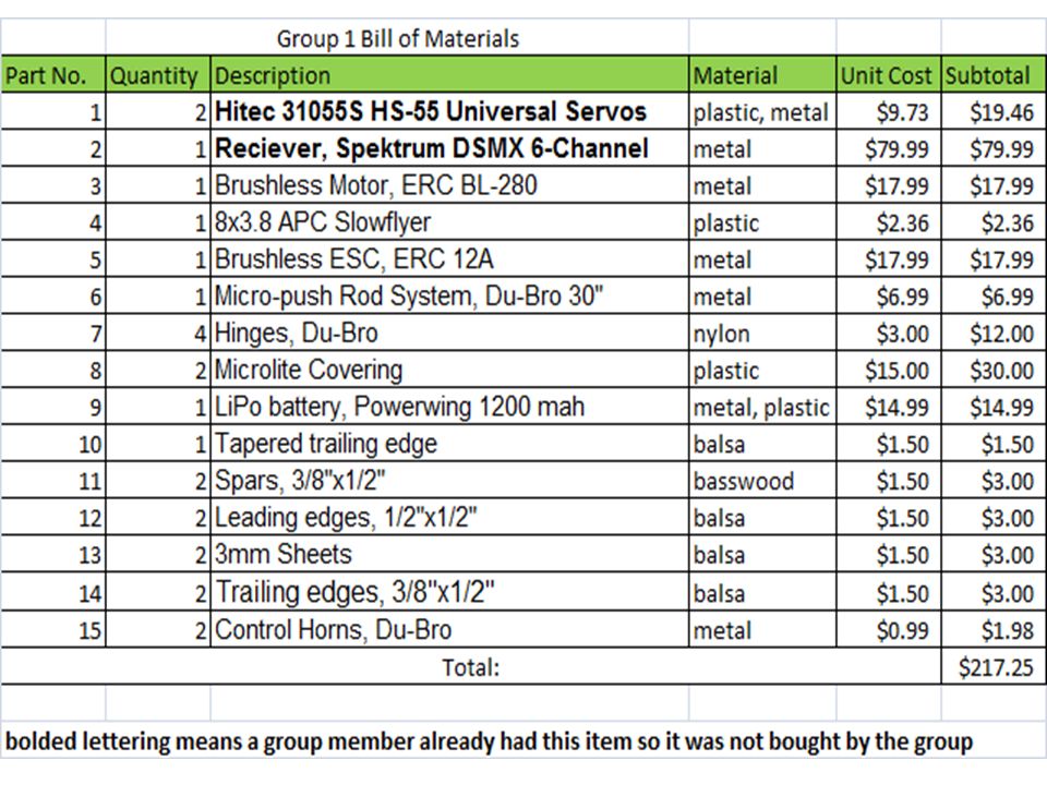
Teamwork Austin – Team Treasurer – Builder and Designer – Written Design Explanation – Pictures Michelle – Team Leader – Bill of Materials – Hand drawn and Creo sketches – Gantt Chart Dylan – Written Analysis – Pictures Lucila – Hand drawn and Creo sketches – Data Table – Written Conclusion Alsia – Written Problems and Solutions – Written Summary Peter – Written Table of Contents

3
Introduction The Micro Aerial Vehicle (MAV) is a model Unmanned Aerial Vehicle (UAV) using microelectronics UAV control commands originate from remote locations, such as a computer system, a pilot in another vehicle, or a technology team miles away We decided to build our MAV from scratch using our background knowledge
 is a model Unmanned Aerial Vehicle (UAV) using microelectronics UAV control commands originate from remote locations, such as a computer system, a pilot in another vehicle, or a technology team miles away We decided to build our MAV from scratch using our background knowledge")
4
Objectives We are tasked with designing and testing a micro aerial vehicle that will: – Cost less than $250 – Fly 5+ minutes without recharging its energy source – Take off from and land on the ground – Can be controlled remotely by a 2.4G Hz radio transmitter in a 100’x50’x30’ space – And weigh less than 450 grams The Mission: Endurance - fly as many figure 8 paths around two pylons separated by 50’ in five minutes.

5
Gantt Chart through Week 8

6
Gantt Chart continued

7
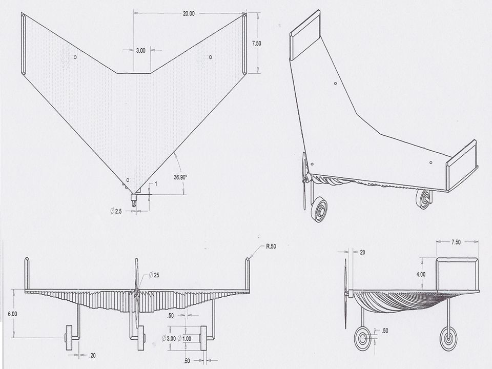
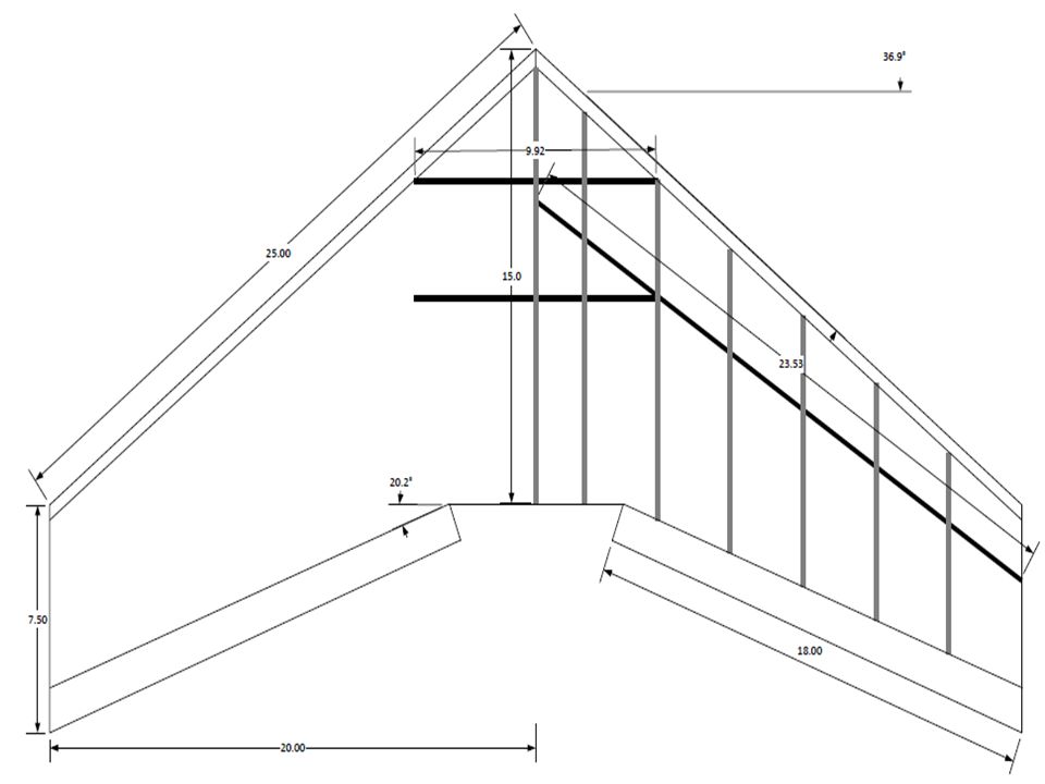
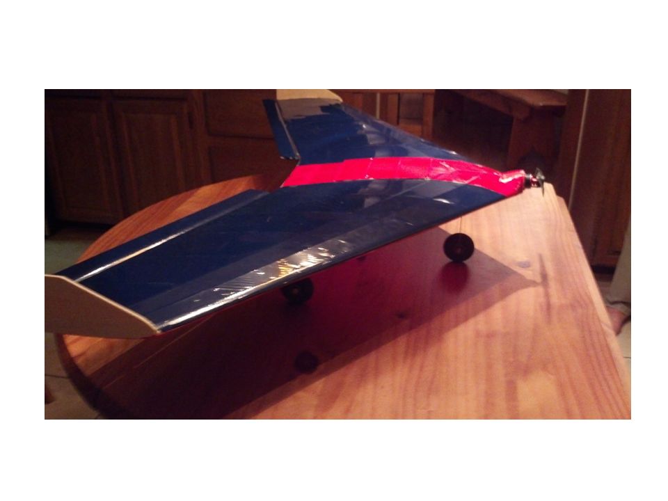
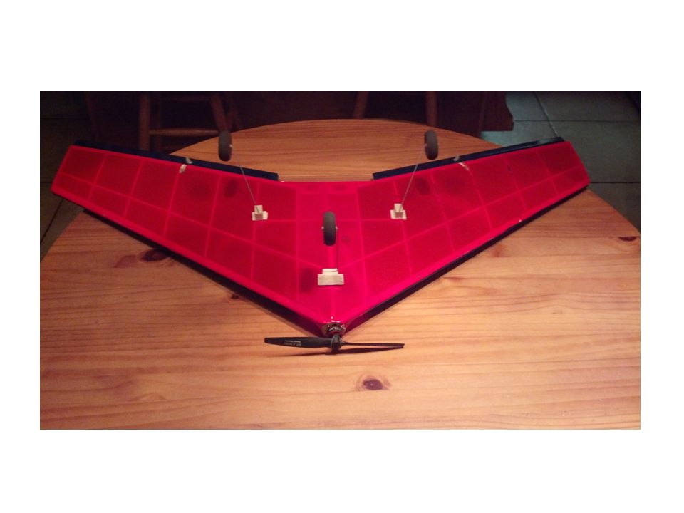
Design - Aircraft Our group chose to design a fixed wing aircraft powered by a brushless motor and dual blade propeller. After some deliberation we decided on a "flying wing" type design because of it's simplistic construction. to keep the plane light, the wing skeleton was constructed out of lightweight balsa sheets and spars, and covered using microlite film to give it shape.

8
Design - Navigation For control of the aircraft, we chose manual control via a 2.4 ghz transmitter. For a flying wing type design, at least 3 channels are required: One for the motor, and two for the elevons. The Spektrum dx6i controller that we already owned was more than adequate for this. Any other navigational method other than radio control would add considerable weight to the aircraft and cause us to exceed our cost requirements.

9
Design - Propulsion For propulsion of the flying wing, we decided to use an electric brushless motor. Brushless motors are lighter and less unwieldy than brushed electric motors and relatively cheap as well. Other choices such as gas motors, pulse jets, lighter than air propulsion are overly complicated, dangerous, or unwieldy for the simplistic nature of the aircraft.

10
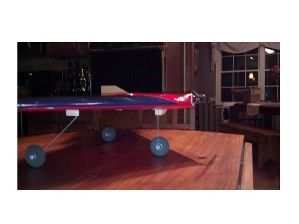
Design – Take Off Mechanism For the take off and landing we utilized a simple three point landing gear. One wheel at the front, and two at either side of the back of the wing. wheeled gear was the only available option if we are to abide by the design constraints.

11
Design – Control Surfaces A flying wing type design has a combination of elevator and ailerons called "elevons". Elevons accomplish the job of both elevators and ailerons simultaneously. a lightweight micro push rod system consisting of a long plastic tube with a flexible wire inside controls the elevons Servos push the wire in and out of the tube, allowing the wire to travel through it even while bent in a curve.

12
Design – Making the Camera Mount to stay light and simple we constructed our camera mount out of balsa and elastic bands. We glued an angled block just forward of the front gear for the camera to rest on, and used two small elastic band to wrap around the block and the camera. With a 20 gram camera, elastic keeps the camera in place during flight and avoids adding any unnecessary weight or additional complications.

13
Design – Securing Hardware To secure hardware components we used a combination of friction, adhesive, and hardware. Control nodes were superglued into the elevons the servos and the motor were secured with small metal screws. The battery and receiver are held in place in tight friction-fit slots cut out of the balsa wood within the control cavity. The micro push rod system is threaded through the ribs of the plane and superglued into place.

14
Parts for Motor Propeller Sub-Assembly

15
Motor Propeller Sub-Assembly

16
Parts for Landing Gear Sub-Assembly

17
Landing Gear and Wheel Sub-Assembly

18
Parts for Wing and Vertical Stabilizer Sub-Assembly

19
Wing and Vertical Stabilizer Sub-Assembly

20
Micro Aerial Vehicle Assembly

22
Analysis: Flight Trainer Chosen The flight trainer that we chose was the Night Vapor RTF model. We chose this model due to its low cost its easy to assemble and fly nature and the instructors recommendation. its maneuverability and construction is similar to the design parameters given.

23
Analysis: Basic Platform Chosen We chose the Flying wing design instead of using a slow stick kit because of prior experience of flying and building. We chose the flying wing design to build from scratch because it is easy to build as opposed to a design with a fuselage. large wing area allows for lots of lift and slow flight. The slight dihedral and swept back wings increases stability of the aircraft. We constructed the plane out of Balsa because it is extremely lightweight and effective to keep the weight of the plane down.

25
We chose to have a Sipkill airflow because it has more lift at a horizontal position than a symmetrical airfoil, also because it needs to be a slow flying aircraft for surveillance. The more lift there is the slower speed is required for flight. Its asymmetrical cambered airfoil allows the aircraft to have more lift slowing it down and making it easy to fly.

26
Flying wing type aircraft use "elevons", which act as ailerons and elevators simultaneously rather than having independent ailerons and elevators. This design is more efficient because it combines the two motions into one element We used a front positioning, "puller" propeller. The vehicle must take off and cannot be thrown, so a rear propeller location would exceed the constraints. A rear propeller would contact the ground unless unwieldy landing gear was used to elevate the wing high off the ground.

27
Analysis: Motor and Servos Chosen We chose the motor because it's lightweight, and rated for planes around 500 grams. it connects to the propeller using rubber rings, making a motor mount unnecessary, thus decreasing the weight of the plane because an item is eliminated. We used the Hitec universal servos that we already had eliminating costs of going to get new ones.

28
Analysis: Battery and Charger Chosen We chose the lightest possible battery that would power that motor for at least 6 minutes at 3/4 throttle by doing the math. The 1200 mah battery provides more than enough time for the plane to fly. the lighestest weight battery has plenty of power fits the weight constraints. the charger comes with the battery providing a less cost scenario.

29
Analysis: Transmitter Chosen We used the Spektrum 6- Channel Receiver as our transmitter because we already had it. This eliminated costs and this receiver is effective and efficient.

30
Analysis: Camera Mount Design We decided to make the camera mount out of balsa material due to its lightweight material and because we used balsa for everything else. The camera mount is a piece of balsa and rubber bands so it can accommodate any kind of DVR. It is lightweight and effective.

31
Completed MAV

35
Problem and Solution #1 Problem: The plane frequently banked left while flying. Solution: We trimmed the left elevon down with the transmitter to create more balance between elevons. This fixed the plane to fly without banking when not purposely turning.

36
Problem and Solution #2 Problem: The 1300 mAh battery would cause plane to exceed weight requirements. Solution: We adopted an 800 mAh battery the weight limit was not exceeded and the plane retained enough charge to finish the 6 minute flight.

37
Problem and Solution #3 Problem: The center of gravity was too far forward, causing the plane to be nose-heavy and dip forward. Solution: The battery pack was moved further backwards on the plane to adjust the center of gravity. This resulted in a smoother flight and better balance within the plane.

38
Problem and Solution #4 Problem: The Deans connecter on the 800 mAh battery was not the same size as the deans connecter on the ESC. Solution: The connecter on the battery was changed to a smaller one that would fit the ESC.

40
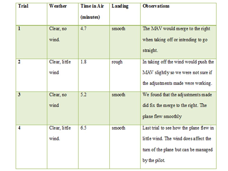
Testing We flew our MAV in clear weather. There was plenty of room to fly on the school football field so there was no issue with space. In the first few trials the MAV would bank slightly to the right. Once the servos were trimmed on the transmitters the MAV had a stable flight. The MAV flew for six and a half minutes and landed smoothly.

42
Conclusion The MAV Flying wing design we built was a success after a few adjustments the servos. We saved money on items one group member already had and components were fairly priced. When training, it took a few trails to get the hang of the remotes correlation to the MAV’s movement; however our teammates were patient and helpful. Our group designed a MAV that can successfully take off from the ground, fly, and land smoothly.

43
This experience will greatly enhance our view with MAV’s, aero dynamics, Creo, and team work for the future to come.

Similar presentations

 is controlled remotely by a hand held transmitter & receiver within the aircraft. The.>")


 with a camera payload ∞ UAV must autonomously navigate with real-time video.>")


 What part of the aircraft that is located on the outer portion of the trailing.>")