Download presentation
Presentation is loading. Please wait.

1
CHÖÔNG 2 Gia cöôøng ñaát yeáu vôùi phöông phaùp troän vôùi chaát keát dính (coät ñaát troän voâi – ciment) BAØI GIAÛNG A Pr.Dr. CHAÂU NGOÏCAÅN

2
Deep Soil Mixing for Contaminant Fixation These photos are from a deep soil mixing (DSM) project for in-situ fixation of contaminants at a site near San Francisco Bay, California, in 1993. The purpose of "in-situ fixation" is to bind the subsurface contaminants within a soil cement matrix. The fixation must be sufficiently strong to prevent the contaminants from being leached out of the cement matrix under future possible combinations of groundwater chemistry and hydraulic gradients. BAØI GIAÛNG A Pr.Dr. CHAÂU NGOÏCAÅN

3
PHAÏM VI ÖÙNG DUÏNG: * OÅn ñònh vaø coá keát maùi doác coù taûi beân treân; thaønh hoá ñaøo * Neàn coù taûi phaân boá ñeàu : ñöôøng boä; ñöôøng saét; baûi chöùa haøng; kho chöùa haøng * Neàn coâng trình coù taûi trung bình : nhaø thaáp taàng; bieät thöï; kho chöùa haøng BAØI GIAÛNG A Pr.Dr. CHAÂU NGOÏCAÅN

4
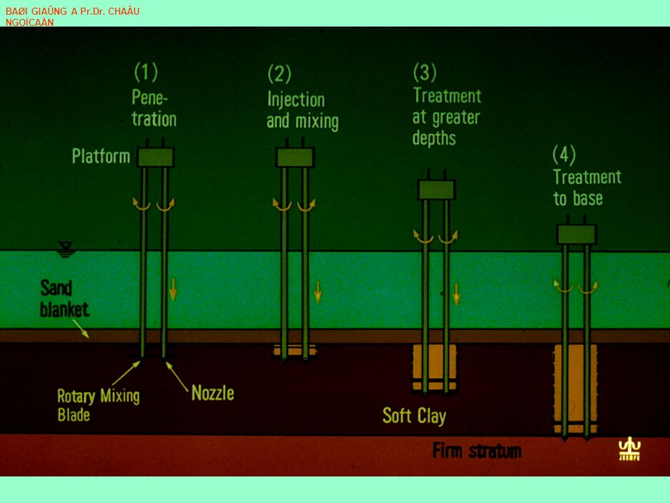
Nguyeân lyù taïo COÏC ÑAÁT- XI-MAÊNG hoaëc VOÂI * Hai hoaëc ba löôõi khoan phaù keát caáu ñaát vaø ñi xuoáng + ñoàng thôøi phuït xi maêng troän vaøo ñaát * Quay ngöôïc löôõi khoan ñeå troän ñeàu ñaát vôùi xi maêng ñoàng thôøi löôõi khoan ñi leân Hai tieán trình naøy ñöôïc laäp ñi laäp laïi treân moãi ñoaïn coïc nhaèm troän ñeàu ñaát vôùi xi maêng BAØI GIAÛNG A Pr.Dr. CHAÂU NGOÏCAÅN

6
This side view of the DSM rig shows the augers out of the ground. BAØI GIAÛNG A Pr.Dr. CHAÂU NGOÏCAÅN

7
An engineer directs the positioning of the augers according to the guide strings that were established by the surveyors. Notice that there are 3 augers that overlap each other. Successful fixation of the contaminants requires that the in-situ soil be entirely and thoroughly mixed with the cementing admixtures BAØI GIAÛNG A Pr.Dr. CHAÂU NGOÏCAÅN

8
This close-up shows that the middle auger is recessed relative to the outer two augers. The grout, which is a mixture of cementing agents and water, is injected through ports near the ends of the augers. BAØI GIAÛNG A Pr.Dr. CHAÂU NGOÏCAÅN

9
Augers are being advanced into the ground BAØI GIAÛNG A Pr.Dr. CHAÂU NGOÏCAÅN

10
Augers continue to mix the soil. Notice that the auger flights do not extend to the ground surface. This allows the augers to mix the soil without carrying it upwards to the ground surface. BAØI GIAÛNG A Pr.Dr. CHAÂU NGOÏCAÅN

11
The H-beam is lowered to a desired depth, and the cable is pulled to open the trap bucket and obtain a sample of the soil mixture. BAØI GIAÛNG A Pr.Dr. CHAÂU NGOÏCAÅN

12
Proprietary admixtures for the grout at this site were delivered by tank and in bags. BAØI GIAÛNG A Pr.Dr. CHAÂU NGOÏCAÅN

13
A batch mixing plant was used to mix the grout (admixtures and water) in proper proportions and to pump it to the DSM rig. The grout was injected through the augers and thoroughly mixed with the soil. The resulting soil mixture later hardens due to cementitious reactions between the admixtures, clay minerals in the soil, and water. This hardened "soil cement" binds or fixates the known contaminants against future transport by seeping groundwater. BAØI GIAÛNG A Pr.Dr. CHAÂU NGOÏCAÅN

14
A backhoe raises a steel H- beam that is equipped with a trap bucket sampler at its bottom end. BAØI GIAÛNG A Pr.Dr. CHAÂU NGOÏCAÅN

15
The retrieved sample is inspected by hand to determine if the soil has been adequately broken down and mixed with the grout. Samples are retained for appropriate lab testing. BAØI GIAÛNG A Pr.Dr. CHAÂU NGOÏCAÅN

16
Single shaft mixing are commonly employed in soil stabilizing purposes having comparatively shallow mixing depth (10m or less). This is called as TENO-COLUMN which a single mixing shaft provided a drilling blade C and mixing blade B, and a stational blade of which length is longer than the other blades. While the mixing rod rotates, two blades B and C are rotated together with the mixing shaft, but the stational blade does not rotate with the mixing shaft. This stational blade functions to prevent soil from turning resulting to improve [Mixing performance] remarkably. BAØI GIAÛNG A Pr.Dr. CHAÂU NGOÏCAÅN

17
These twin mixing shafts have each one mixing blade and one drilling blade which are positioned at different height. Twin mixing rods rotate in relative direction as shown in the illustration. A cement slurry injected at their rod ends is mixedwith soil in-place. Two overlapped columns are constructed effectively at one time which assures a wider stabilized area. This technique is commonly employed to construct a diaphragm wall for soil retaining walls, water tight walls, etc. BAØI GIAÛNG A Pr.Dr. CHAÂU NGOÏCAÅN

18
This co-axial shaft mixing technique gives a high mixing performance even if the mixing diameter exceeds 1500mm. The inner shaft rotates at low speed for performing a better digging performance and the outer shaft rotates rather high speed for performing a better mixing efficiency. BAØI GIAÛNG A Pr.Dr. CHAÂU NGOÏCAÅN

19
Deep Soil Mixing for Reinforcement & Strengthening of Soils at Port of Oakland, CA Deep soil mixing (DSM) was used to provide reinforcement and strengthening of soils at the Port of Oakland, California. These photos, from 2001, illustrate some of the equipment used and the characteristics of the hardened soil cement as exposed in excavations. BAØI GIAÛNG A Pr.Dr. CHAÂU NGOÏCAÅN

20
Two deep soil mixing rigs, one in the foreground and one in the background, are working simultaneously at this time. The rigs are constructing a grid of soil-cement walls by constructing overlapping columns. BAØI GIAÛNG A Pr.Dr. CHAÂU NGOÏCAÅN

21
Each rig is equipped with three overlapping mixing paddles (or augers). The mixing paddles are of limited length so that they do not carry soil up to the ground surface, but rather continually mix the soil at the depth to which the paddles are lowered. Grout, in this case a mixture of water and cementing agents, will be pumped through ports in the mixing paddles, and subsequently mixed with the soil. In this photo, the mixing paddles are just beginning to enter into the soil. BAØI GIAÛNG A Pr.Dr. CHAÂU NGOÏCAÅN

22
The mixing paddles periodically require maintenance due to wear and abrasion on many of the parts. BAØI GIAÛNG A Pr.Dr. CHAÂU NGOÏCAÅN

23
A batch plant provides automated mixing of the grout materials, which is then pumped to the deep mixing rigs. Data acquisition and computer monitoring systems keep detailed records of mixing and pumping parameters. BAØI GIAÛNG A Pr.Dr. CHAÂU NGOÏCAÅN

24
A coring rig is used to obtain solid cores of the hardened soil- cement. The cores are used in various tests as part of the quality control program. BAØI GIAÛNG A Pr.Dr. CHAÂU NGOÏCAÅN

25
The grid of soil-cement columns is exposed at this location. The piles within the grid will support a wharf that is being constructed. The grid of soil-cement walls extends down through soft soils into harder, competent soils, and acts to increase the stability of the channel slope. BAØI GIAÛNG A Pr.Dr. CHAÂU NGOÏCAÅN

26
A close-up view of the hardened soil-cement at one location shows pockets of clay within the soil-cement matrix. These clay pockets occur where there has been insufficient mixing: Note that this example comes from an elevation where the soil-cement was going to be excavated and so it intentionally was not mixed thoroughly BAØI GIAÛNG A Pr.Dr. CHAÂU NGOÏCAÅN

27
Each vertical run of the mixing rig produces 3 overlapping columns, and these columns must overlap with adjacent sets of columns to produce a continuous wall. At this one location, there is a T-intersection of the soil- cement columns where the desired overlap was not achieved. Accurate positioning is a key element of quality control, but allowance must be made for occasional defects. BAØI GIAÛNG A Pr.Dr. CHAÂU NGOÏCAÅN

28
The overlapping connection between soil-cement columns may or may not form strong bonds depending on several factors. At this location, a "cold joint" at a T-intersection of soil-cement walls has been slightly separated. Such cold joints are weak in tension and will have reduced shear resistance. BAØI GIAÛNG A Pr.Dr. CHAÂU NGOÏCAÅN

29
This is a side view of soil-cement columns exposed by an excavation. Notice that the columns are horizontally stratified, reflecting the variation in soil type with depth. The diagonal cracks that can be seen in the columns are primarily due to impacts by the backhoe that made the excavation. BAØI GIAÛNG A Pr.Dr. CHAÂU NGOÏCAÅN

30
In-situ cement mixing of soft clay deposits BAØI GIAÛNG A Pr.Dr. CHAÂU NGOÏCAÅN

36
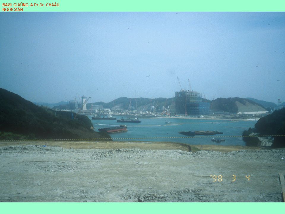
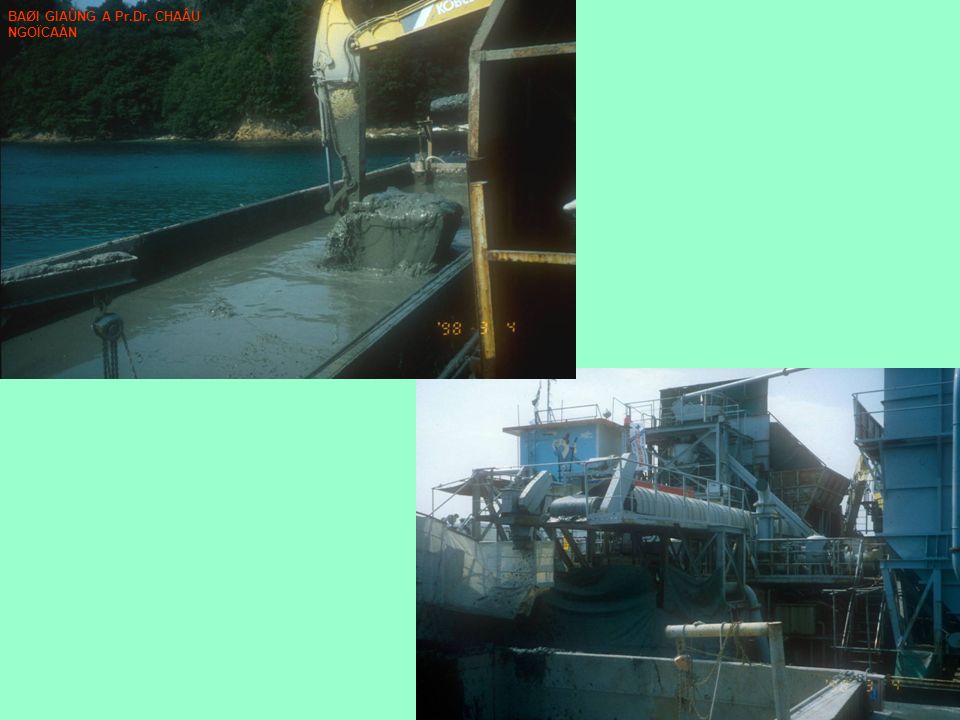
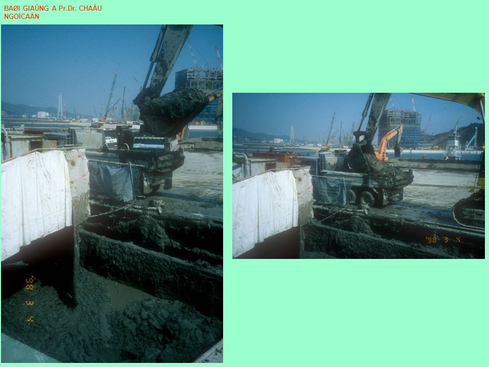
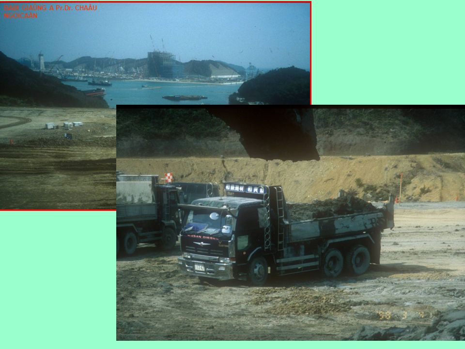
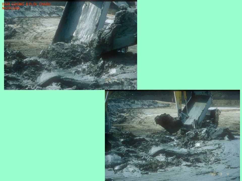
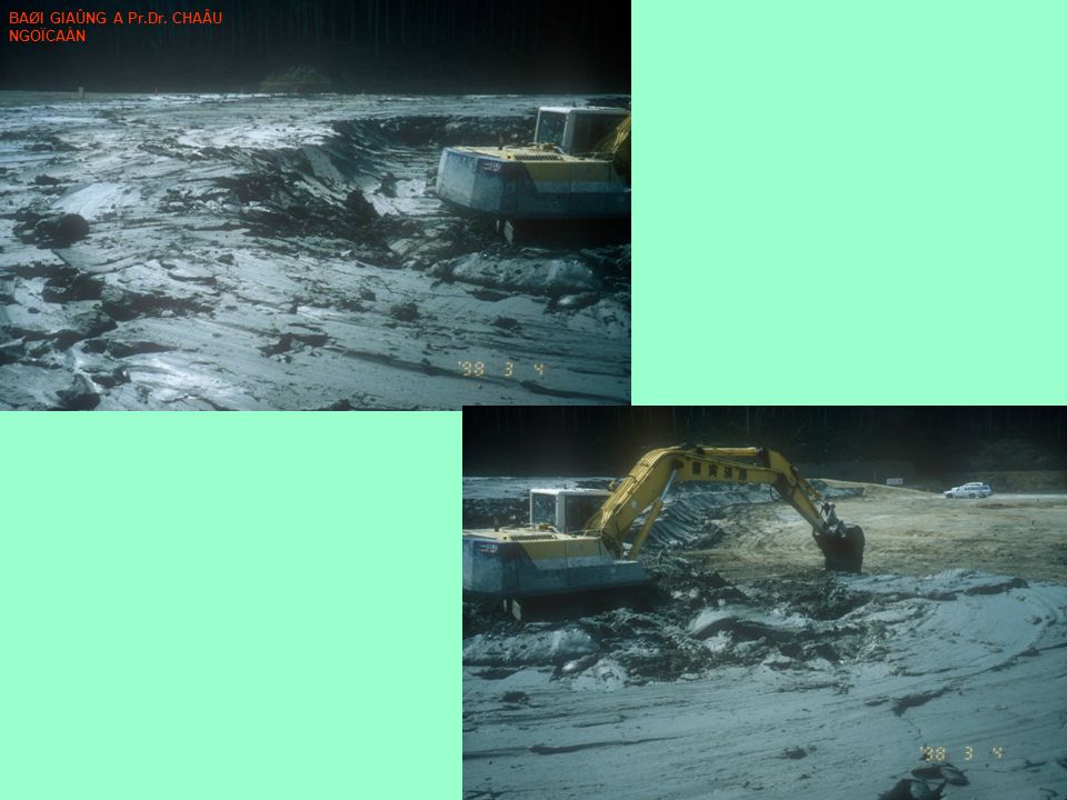
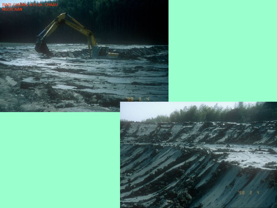
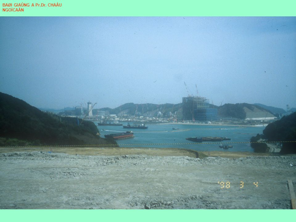
Embankment of a high-water content marine clay mixed with a small amount of cement 1)A very soft marine clay (a water content of 49.7 %), dredged from the nearby seabed. 2) Mixed with a small amount of cement (3.5 % in weight of clay) to use as the backfill for a 50 m-high embankment. Dredging for reclamation using sand and gravel to support an electric power plant High embankment BAØI GIAÛNG A Pr.Dr. CHAÂU NGOÏCAÅN
 Mixed with a small amount of cement (3.5 % in weight of clay) to use as the backfill for a 50 m-high embankment. Dredging for reclamation using sand and gravel to support an electric power plant High embankment BAØI GIAÛNG A Pr.Dr. CHAÂU NGOÏCAÅN.")
46
Compaction Grouting - General Information BAØI GIAÛNG A Pr.Dr. CHAÂU NGOÏCAÅN

47
This series of schematics illustrates the general procedures in the bottom-up technique of compaction grouting. The first step, shown here, is to install grout pipes using drilling or driving techniques. BAØI GIAÛNG A Pr.Dr. CHAÂU NGOÏCAÅN

48
The mortar-like grout, injected through the pipes, displaces the surrounding soil. The grout pipe is then lifted some distance (0.3 to 1.5 m), and the injection process is repeated. BAØI GIAÛNG A Pr.Dr. CHAÂU NGOÏCAÅN
, and the injection process is repeated. BAØI GIAÛNG A Pr.Dr. CHAÂU NGOÏCAÅN.")
49
Injection in "stages" continues until the target layer has been treated. Grouting can stiffen and strengthen the soil layer by increasing its density, increasing the lateral stresses, and acting as a reinforcement. Grouting may also be used to produce controlled heaving of the ground surface to re-level a structure that has been damaged by differential settlements. BAØI GIAÛNG A Pr.Dr. CHAÂU NGOÏCAÅN

50
These compaction grout bulbs were excavated as part of a demonstration project by Denver Grouting (now with Hayward Baker). These four grout bulbs were from the same grout mix, and are all relatively regular in shape. BAØI GIAÛNG A Pr.Dr. CHAÂU NGOÏCAÅN

51
These four grout bulbs were from a more "mobile" (more fluid like) grout mix which allowed it to form winged- shaped bulbs. BAØI GIAÛNG A Pr.Dr. CHAÂU NGOÏCAÅN

52
This schematic shows six different possible applications for compaction grouting. BAØI GIAÛNG A Pr.Dr. CHAÂU NGOÏCAÅN

53
Compaction Grouting Compaction grouting was performed at a site in Sacramento, California, in 1992, to improve the liquefaction resistance of a underlying sand layer. Compaction grout does not permeate a soil, but rather displaces it. The shearing of the surrounding soil as it is displaced by the compaction grout can result in densification if the confining stresses (depth of overburden) are sufficient. See "Compaction grouting - General Information" for more details on the processes involved. BAØI GIAÛNG A Pr.Dr. CHAÂU NGOÏCAÅN
 are sufficient. See Compaction grouting - General Information for more details on the processes involved. BAØI GIAÛNG A Pr.Dr. CHAÂU NGOÏCAÅN.")
54
At this site, an air percussion rig was used to advance grout pipes to the desired depth. The driller is making sure the pipes are vertical before starting to drive them. BAØI GIAÛNG A Pr.Dr. CHAÂU NGOÏCAÅN

55
Silty sand was the main ingredient in the compaction grout. The other components were Portland cement and water. BAØI GIAÛNG A Pr.Dr. CHAÂU NGOÏCAÅN

56
The silty sand is placed in a hopper bin on the back of this mobile mixing truck. BAØI GIAÛNG A Pr.Dr. CHAÂU NGOÏCAÅN

57
Portland cement is placed in a separate hopper bin BAØI GIAÛNG A Pr.Dr. CHAÂU NGOÏCAÅN

58
The truck mixes the silty sand, Portland cement, and water (and sometimes other additives on other jobs) together in set proportions. The final grout mixture is delivered from the truck along this screw auger chute. BAØI GIAÛNG A Pr.Dr. CHAÂU NGOÏCAÅN

59
The grout is fed into a mobile grout pump BAØI GIAÛNG A Pr.Dr. CHAÂU NGOÏCAÅN

60
The hopper of the grout pump has rotating blades that continuously mix the grout. BAØI GIAÛNG A Pr.Dr. CHAÂU NGOÏCAÅN

61
The grout pump's hopper is filled with grout BAØI GIAÛNG A Pr.Dr. CHAÂU NGOÏCAÅN

62
A slump cone test, just like performed on a Portland cement concrete mix, is usually performed on bulk samples of the grout mix. This thick grout mixture will not permeate the pores of the soil that it is injected into, but will rather displace it. BAØI GIAÛNG A Pr.Dr. CHAÂU NGOÏCAÅN

63
Grout is pumped from the grout pump (in the background) through a hose that connects to the top of a preinstalled grout pipe (left-front of photo). The grout pipe is connected to a hydraulic jack that progressively pulls the pipe out of the ground. Grouting is periodically stopped to remove a segment of the grout pipe as necessary. The grout pressure is measured by a gage near the top of the grout pipe, with pressures of 50 to 600 psi being common. BAØI GIAÛNG A Pr.Dr. CHAÂU NGOÏCAÅN

64
Close up of the hydraulic jack gripping onto the grout pipe. The pipe is usually pulled in increments of one, two, or three feet. This is called the "bottom-up" method because grouting begins at the bottom of the hole and progresses upwards. Measurements of ground surface heave, grouting pressure, and grout injection volumes are used to determine when the grout pipe should be further withdrawn. BAØI GIAÛNG A Pr.Dr. CHAÂU NGOÏCAÅN

65
Injection for Expansive Soils Potential damage from expansive soils can sometimes be avoided by treating the ground using injection methods. The injected fluid may be water (for preswelling the ground), lime, or a chemical solution (e.g., potassium). BAØI GIAÛNG A Pr.Dr. CHAÂU NGOÏCAÅN
, lime, or a chemical solution (e.g., potassium). BAØI GIAÛNG A Pr.Dr. CHAÂU NGOÏCAÅN.")
66
An injection unit with multiple injectors. BAØI GIAÛNG A Pr.Dr. CHAÂU NGOÏCAÅN

67
Rigs with multiple injectors deliver the stabilizing fluid into the soil. The fluid will prefer to travel into cracks and fissures. The extent to which the fluid permeates the soil uniformly depends on the permeability of the soil, the nature of fissuring, and the injection procedures. In any event, sealing fissures and cracks can be effective in improving the volumetric-stability of the soil mass. BAØI GIAÛNG A Pr.Dr. CHAÂU NGOÏCAÅN

68
Jet Grouting Jet grouting was used to reduce seepage and prevent piping erosion of a levee in Stockton, California, in 1999. Overlapping jet grout columns were used to form a cut-off wall in the problem sand layer. The cut-off wall was located beneath the levee crest between depths of 4 and 9 m and extended along the levee for about 230 m. BAØI GIAÛNG A Pr.Dr. CHAÂU NGOÏCAÅN

69
This schematic illustrates the jet grouting process. The jet grouting rods are first positioned to the target depth using some boring technique. Jets of air, water, and/or grout are simultaneously used to progressively erode the native soil and replace it with a soil-grout (cement) mixture. Jet grouted columns or panels can be overlapped to produce subsurface walls of soil-cement. BAØI GIAÛNG A Pr.Dr. CHAÂU NGOÏCAÅN
 mixture. Jet grouted columns or panels can be overlapped to produce subsurface walls of soil-cement. BAØI GIAÛNG A Pr.Dr. CHAÂU NGOÏCAÅN.")
70
The mixing plant for the jet grouting operations was located in an open area more than a couple hundred meters from the treatment zone. The rectangular tanks on the right side are settling tanks for the grout spoil materials. The tall, blue tank and other smaller tanks supply grout ingredients, and the yellow equipment to the left side is for mixing and pumping. BAØI GIAÛNG A Pr.Dr. CHAÂU NGOÏCAÅN

71
This unit mixes the grout in batches. The supporting legs of the unit have been strain gaged to measure the weight of materials that pass through the unit in each batch. BAØI GIAÛNG A Pr.Dr. CHAÂU NGOÏCAÅN

72
The jet grouting drill rig is visible further down the crest of the levee. The white pipe along the right side of the levee carries grout to the rig, and the gray pipe beside it carries spoil materials back to the settling tanks. BAØI GIAÛNG A Pr.Dr. CHAÂU NGOÏCAÅN

73
This track-mounted jet grouting rig is able to fit in the constrained area of the levee crest. An overflow tank is position around the drill stem at the ground surface, and catches the spoil materials that are displaced by the grouting process. The captured spoils are pumped back to the batch plant through the gray pipe laying to the left of the rig. BAØI GIAÛNG A Pr.Dr. CHAÂU NGOÏCAÅN

74
A side view of the jet grouting rig. BAØI GIAÛNG A Pr.Dr. CHAÂU NGOÏCAÅN

75
This is a "double-tube" jet grout monitor with an attached drill bit. It is shown in the upright position, standing on the drill bit. The two concentric "tubes" at the top are attached to the rods and allow for conveyance of high pressure grout through the inner annulus and high pressure air through the outer annulus, simultaneously. The grout and air exit through the side jet ports (one on each side of the monitor) with the air "shrouding" the grout. The two side jets usually expel grout and air at the same time. One side jet can be blocked off, if desired, to allow jet grouting in one direction only. "Triple-tube" systems allow for the simultaneous use of water, grout, and air. They would be characterized by three concentric "tubes" at the top of the monitor rather than the two tubes shown here. BAØI GIAÛNG A Pr.Dr. CHAÂU NGOÏCAÅN
 with the air shrouding the grout. The two side jets usually expel grout and air at the same time. One side jet can be blocked off, if desired, to allow jet grouting in one direction only. Triple-tube systems allow for the simultaneous use of water, grout, and air. They would be characterized by three concentric tubes at the top of the monitor rather than the two tubes shown here. BAØI GIAÛNG A Pr.Dr. CHAÂU NGOÏCAÅN.")
76
In-situ cement mixing of soft clay deposits BAØI GIAÛNG A Pr.Dr. CHAÂU NGOÏCAÅN

Similar presentations


 19 August 2014.>")


 Session 11 Course: S0892 - Ground Improvement Method Year: 2010.>")


 to the ground within allowable settlement criteria.>")
 Session 2 - 7>")


