Download presentation
Presentation is loading. Please wait.

1
Bio-inspired locomotion control of hexapods
Alessandro Rizzo

2
Outline Bio-inspired robotics
CNN-based Central Pattern Generators (CPG) CPG and sensory feedback The VLSI CNN-based CPG chip High-level control HexaDyn and future works
 CPG and sensory feedback. The VLSI CNN-based CPG chip. High-level control. HexaDyn and future works.")
3
BIO-INSPIRED ROBOTS Synergies from various disciplines (robotics, neuroscience, biology, ethology) Robotic animal models to a major understanding of biological behaviors Biological inspiration to build efficient robots

4
REFLEXES IN THE STICK INSECT
Stepping reflex (A) Elevator reflex (B) Searching reflex (C) Local reflexes improve rough terrain locomotion in a hexapod robot
 Elevator reflex (B) Searching reflex (C) Local reflexes improve rough terrain locomotion in a hexapod robot.")
5
Cosa hanno in comune questi animali e il robot?

7
CPG: a paradigm for bio-inspired locomotion control
Animals move according to a pattern of locomotion This pattern is due to the pattern of neural activities of the so-called CPG This paradigm can be used to control a legged robot

8
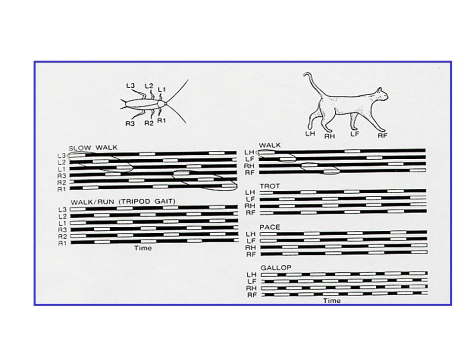
Basic definitions for gait analysis
Transfer phase (swing phase, return stroke) Support phase (stance phase, power stroke) Cycle time T Duty factor bi Leg phase fi Leg stride l Leg stroke R Stroke pitch Effective body length Gait matrix Gait formula Dimensionless foot position Dimensionless initial foot position Kinematic gait formula Event Singular gait Regular gait Symmetric gait Support pattern Periodic gait Stability margin Front stability margin (rear stability margin) Gait stability margin Stability margin normalized to stride Gait Gait Anatomy/ Structure Stability skip
 Support phase (stance phase, power stroke) Cycle time T. Duty factor bi. Leg phase fi. Leg stride l. Leg stroke R. Stroke pitch. Effective body length. Gait matrix. Gait formula. Dimensionless foot position. Dimensionless initial foot position. Kinematic gait formula. Event. Singular gait. Regular gait. Symmetric gait. Support pattern. Periodic gait. Stability margin. Front stability margin (rear stability margin) Gait stability margin. Stability margin normalized to stride. Gait. Gait. Anatomy/ Structure. Stability. skip.")
9
Locomotion Patterns – Alternating tripod
Tstance (L1) TRIPOD GAIT Duty Factor (df) Leg phases The swing (flexion phase) depends on the mechanics of the limb
 TRIPOD GAIT. Duty Factor (df) Leg phases. The swing (flexion phase) depends on the mechanics of the limb.")
10
Locomotion Patterns – Medium Gait
Tstance (L1) MEDIUM GAIT T Duty Factor (df) Leg phases
 MEDIUM GAIT. T. Duty Factor (df) Leg phases.")
11
Locomotion Patterns – Tetrapod Gait
Tstance (L1) TETRAPOD GAIT T Duty Factor (df) Leg phases
 TETRAPOD GAIT. T. Duty Factor (df) Leg phases.")
12
CPG: a paradigm for bio-inspired locomotion control
Animals move according to a pattern of locomotion This pattern is due to the pattern of neural activities of the so-called CPG This paradigm can be used to control a legged robot

13
The Central Pattern Generator
Definition: A neural circuit that can produce a rhythmic motor pattern with no need for sensory feedback or descending control Proof of existence: remove sensory feedback, descending control and elicit motor pattern CPG have been demonstrated in all animals to date for rhythmic movements that are essential for survival Feedforward control CPG Environment Effector Organs Higher Control Sensory feedback Reflex Feedback Central Feedback The motor system

14
Neurons and motor-neurons
Action potential (spike) Beating, Bursting, Silent state Frequency coding Synapses: chemical, gap junctions
 Beating, Bursting, Silent state. Frequency coding. Synapses: chemical, gap junctions.")
15
Neural Control of Muscles
vertebrates … Motor-neuron Muscle fiber … arthropods Motor-neuron Muscle fiber …

16
Flexor Extensor Pair Block
antagonistic pair: flexor – extensor flexor – extensor modeled by a CNN-based motor unit called CNN neuron more…

17
A CPG-based control system
The CPG is realized by a network of coupled nonlinear oscillators through CNNs Q: How to design a CNN network generating a given pattern? A: Exploit the analogy with the biological case (synapses, motor-neurons…) A: Reduce the complexity of the problem 1,2 1,1 2,1 3,1 3,2 2,2
 A: Reduce the complexity of the problem. 1,2. 1,1. 2,1. 3,1. 3,2. 2,2.")
18
A CPG-based control system
Ring of N neurons: each neuron is connected to its neighbor with an excitatory (or inhibitory) synapse in a well defined direction (clockwise or counterclockwise) The behavior of this kind of network for a suitable valuable of the synaptic weight is a well-defined pattern (traveling wave) The oscillators are synchronized The phase lags between adjacent oscillators are constant 1,2 1,1 2,1 3,1 2,2 3,2
 synapse in a well defined direction (clockwise or counterclockwise) The behavior of this kind of network for a suitable valuable of the synaptic weight is a well-defined pattern (traveling wave) The oscillators are synchronized. The phase lags between adjacent oscillators are constant. 1,2. 1,1. 2,1. 3,1. 2,2. 3,2.")
19
Examples of locomotion patterns with Multi-Template Approach CNN
Waveforms (SC circuit) Fast Gait L3 R2 L1 R1 R3 L2 Slow gait R1 L2 R3 L1 R2 L3 UNIVERSITY OF CATANIA, DEES, SYSTEM AND CONTROL GROUP P. Arena, L. Fortuna, M. Frasca
 Fast Gait. L3. R2. L1. R1. R3. L2. Slow gait. R1. L2. R3. L1. R2. L3. UNIVERSITY OF CATANIA, DEES, SYSTEM AND CONTROL GROUP. P. Arena, L. Fortuna, M. Frasca.")
20
Design of CNN-based CPG From Reaction-Diffusion Equations to inhibitory/excitatory connections
Skip this section

21
The Central Pattern Generator
The biological paradigm Pattern of neural activities Pattern of rhythmic movements Application in the bio-inspired robotics: the CPG controls the locomotion of an hexapod robot CPG Environment Effector Organs Higher Control Sensory feedback Reflex Feedback Central Feedback Motor System CNN realization

22
RD-CNN as CPG for an hexapod robot
Reaction-diffusion equation CNN implementation of the nonlinear medium Autowaves (slow-fast dynamics) Reorganization of the slow part when the pattern is switched into another one Turing patterns in the higher control level The design of CPG in which also chemical synapses are involved is considered in the following
 Reorganization of the slow part when the pattern is switched into another one. Turing patterns in the higher control level. The design of CPG in which also chemical synapses are involved is considered in the following.")
23
The Neuron Model - Slow-Fast CNN Neuron
Equations & Parameters Behavior y1(t), y2(t) ok
, y2(t) ok.")
24
Existence of a periodic orbit
Poincaré-Bendixson theorem: This theorem is a powerful tool to establish the existence of periodic orbits in 2D flows. It states that if R is a closed region that does not contain fixed points for the vector field x=f(x) and a trajectory C confined in R does exist, then R contains a closed orbit (and either C is itself the closed orbit or spirals toward to it).
 and a trajectory C confined in R does exist, then R contains a closed orbit (and either C is itself the closed orbit or spirals toward to it).")
25
Leg Controller Control of a 2 DOF leg: 1 CNN neuron CNN neuron a=y2
1,1 a=y2 b=y1 a b a1 a2 2 DOF leg AEP PEP X H stance swing A C D B

26
Cellular Neural Networks - Two-layer CNN equations
MxN Two-layer CNN cell equations Neighbourhood PWL Output Scheme of a CNN layer 1 -1 y(x) x 1,2 1,1 2,1 3,1 3,2 2,2
 x. 1,2. 1,1. 2,1. 3,1. 3,2. 2,2.")
27
The Synapse Model - Chemical Synapse for the Slow-Fast Neuron
with excitatory synapse inhibitory synapse Simplified Chemical Synapse (excitatory and inhibitory) Template Simplified Delayed Chemical Synapse (excitatory and inhibitory) Template y1(t), y2(t) Tc
 Template. Simplified Delayed Chemical Synapse (excitatory and inhibitory) Template. y1(t), y2(t) Tc.")
28
CNN Multi-Template Approach - Guidelines
Definitions: N = number of pattern steps • n = number of legs ring of N neurons = each neuron is connected to its neighbor with an excitatory (or inhibitory) synapse in a well defined direction (clockwise or counterclockwise) Guidelines Create a ring of N neurons Add the n-N neurons by using synchronisation via “coupling” or synchronisation via “duplicating” Choose the synaptic weights
 synapse in a well defined direction (clockwise or counterclockwise) Guidelines. Create a ring of N neurons. Add the n-N neurons by using synchronisation via coupling or synchronisation via duplicating Choose the synaptic weights.")
29
Rings of N Slow-Fast Neurons
Inhibitory synapses: (a) connections on the layer: A11… (b) connections between layers: A21... (delayed synapses) The behavior can depend on initial conditions In the case (b) [“delayed synapse”] patterns with traveling waves in a well defined direction are obtained (a) (b)
 connections on the layer: A11… (b) connections between layers: A21... (delayed synapses) The behavior can depend on initial conditions. In the case (b) [ delayed synapse ] patterns with traveling waves in a well defined direction are obtained. (a) (b)")
30
Adding the n-N neurons Synchronisation via “coupling”
Synchronisation via “duplicating” B C A B’ C’ Neuron B and neuron B’ are synchronised because they belong to rings that have the same number of cells and share a neuron B C A B’ ... Neuron B’ and neuron B have the same synaptic inputs

31
MTA-CNN: An Example - The Caterpillar Gait
Hexapod L1 R3 1,2 1,1 2,1 3,1 3,2 2,2 R2 L2 L3 R1 Two layer 3x2 CNN Scheme of the locomotion pattern: Caterpillar for six legged robots (right and left legs move in synchrony) N=3 R3 L1 R2 Guidelines (1) Create a ring of N neurons
 N=3. R3. L1. R2. Guidelines (1) Create a ring of N neurons.")
32
MTA-CNN: An Example - The Caterpillar Gait
Guidelines (2) Add the n-N=3 neurons by using synchronisation via “coupling” or synchronisation via “duplicating” R3 L1 R2 L3 R1 L2 R3 L1 R2 L3 R1 L2 R3 L1 R2 Synchronisation by duplicating synapses 1 and 2. Thus, neuron R2 is synchronised with L2 1 1 1 2 2 2 Guidelines (3) Choose the synaptic weights R3 L1 R2 L3 R1 L2 e e/2
 Add the n-N=3 neurons by using synchronisation via coupling or synchronisation via duplicating R3. L1. R2. L3. R1. L2. R3. L1. R2. L3. R1. L2. R3. L1. R2. Synchronisation by duplicating synapses 1 and 2. Thus, neuron R2 is synchronised with L Guidelines (3) Choose the synaptic weights. R3. L1. R2. L3. R1. L2. e. e/2.")
33
MTA-CNN: An Example - The Caterpillar Gait
Firing Sequence CNN Implementation: synaptic connections are established by the feedback templates, these templates depend on the cell position (i.e. they are space-variant) L1 R3 L1 R3 L1 R3 R2 L2 R2 L2 R2 L2 L3 R1 L3 R1 L3 R1
 L1. R3. L1. R3. L1. R3. R2. L2. R2. L2. R2. L2. L3. R1. L3. R1. L3. R1.")
34
MTA-CNN: An Example - The Caterpillar Gait
Simulation Results (SPICE) L2 R2 L1 R1 L3 R3
 L2 R2. L1 R1. L3 R3.")
35
Changing the locomotion pattern
Other locomotion patterns have been implemented (the fast gait, the medium gait and the slow gait) To change a locomotion pattern a new set of template should be loaded, while the network structure is not varied L1 R3 (a) R2 L2 L3 R1 L1 R3 (b) R2 L2 L3 R1 L1 R3 (c) R2 L2 L3 R1
 To change a locomotion pattern a new set of template should be loaded, while the network structure is not varied. L1. R3. (a) R2. L2. L3. R1. L1. R3. (b) R2. L2. L3. R1. L1. R3. (c) R2. L2. L3. R1.")
36
Conclusions A new approach for the design of CNN based CPG to control artificial locomotion has been presented It includes a model of chemical synapses A neighborhood of r=1 is always used Each leg is always driven by the same cell in all the gaits Several locomotion patterns have been successfully implemented on a hexapod robot

37
CPG and feedback Observation: The feedback is fundamental for animal (and legged robot) locomotion How to implement sensory feedback?

38
CPG & Feedback from Sensors
Environment Effector Organs Higher Control Sensory feedback Reflex Feedback Central Feedback Focus of this work is how to include the sensor feedback in the CNN-based CPG

39
Braitenberg vehicles + + Sensors Direct coupling sensor/motor
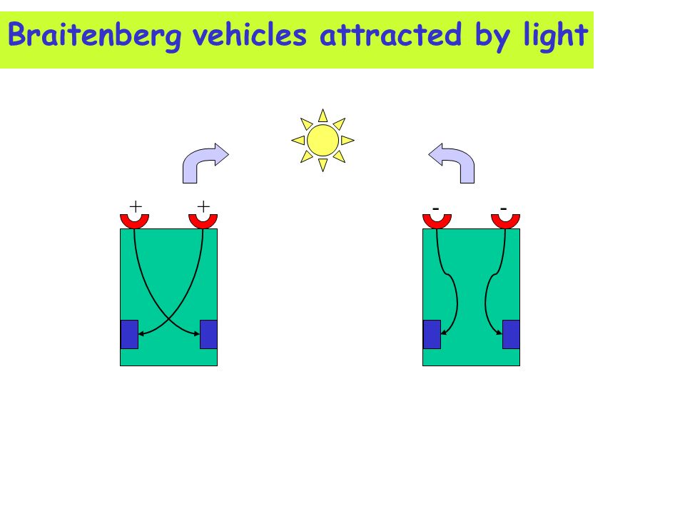
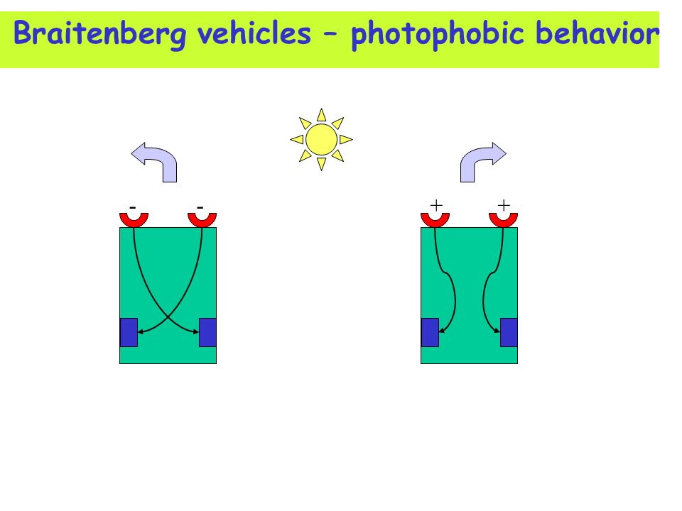
The speed of the motor is changed according to the output of the sensor Excitatory/inhibitory connections “+” increase the speed “-” decrease the speed Behavior of the vehicles + + Wheels

40
Braitenberg vehicles attracted by light
+ + - -
41
Braitenberg vehicles – photophobic behavior
- - + +
42
The principles underlying Braitenberg
vehicles are used to implement feedback in CNN-based CPG

43
CNN based CPG: obstacle avoidance
Control of direction: including sensor feedback in the CPG for obstacle avoidance as in Braitenberg photophobic vehicle - To this aim the dynamical behavior of the CNN cells controlling the mid legs is changed by acting on the bias parameter

44
Dynamics of the CNN cell
Nullclines i2=0.34 i2=0.35 i2=0.36

45
Critical value of the parameter i2
x1 x2 Jacobian of the system for y1=-1

46
Period of oscillations T versus bias values
Continuous line Diamonds: Numerical data

47
CNN-based CPG with sensor feedback
obstacle SLX SRX L1 R1 R2 L2 obstacle L3 R3 The hexapod is equipped with two sensors (measuring the distance from an obstacle) Feedback from sensors is included in the CNN-based CPG
 Feedback from sensors is included in the CNN-based CPG.")
48
Control Scheme CNN CPG HEXAPOD antennae output Simulation tools
(MATLAB) HEXAPOD (VISUAL NASTRAN) antennae output Simulation tools The CPG is implemented in MATLAB A dynamical simulator of the hexapod robot is provided by VisualNastran
 HEXAPOD. (VISUAL NASTRAN) antennae output. Simulation tools. The CPG is implemented in MATLAB. A dynamical simulator of the hexapod robot is provided by VisualNastran.")
49
Results Video

50
Signals from CPG

51
The CNN-based CPG Chip Control of the oscillation frequency
Analog Core CNN-based CPG Digital Control Control of the oscillation frequency Clock frequency Switched Capacitors Implementation

52
Feedback signals in the CNN-based CPG Chip
SC OSC SENSORS A/D DIGITAL CONTROL 1 2 4 3 1 Switched Capacitors Clock 2 Bias control signal 3 Topology (connections) control signal 4 Frequency clock adjust signal Speed control (clock frequency) Direction control (bias of the middle CNN cells) Choice of the gait (choice of the connections)
 control signal. 4 Frequency clock adjust signal. Speed control (clock frequency) Direction control (bias of the middle CNN cells) Choice of the gait (choice of the connections)")
53
Experimental results Oscillation frequency Speed control
Locomotion patterns Direction control

54
Single cell behaviour fc=10kHz fc=100Hz

55
Frequency range 100mHz-3MHz
Large variations of the clock frequency allows the control of the stepping frequency

56
Speed control Small variations of the clock frequency allows the control of the gait speed Measured period and simulated period of oscillations

57
Locomotion patterns Cell Set of Connections 3 2 1
1 Switched Capacitance Clock 2 Bias control signal 3 Topology (connections) control signal Cell ANALOG OUTPUTS Set of Connections DIGITAL INPUTS 2 3 SC CLOCK 1
 control signal. Cell. ANALOG. OUTPUTS. Set of. Connections. DIGITAL. INPUTS SC CLOCK. 1.")
58
Fast Gait fc=100Hz R1 L1 R2 L3 R3 L2 fc=1kHz

59
Direction control R1 L1 R2 L3 R3 L2 SRX SLX

60
High-level control A CNN based Biomorphic Adaptive Robot
Attitude control through CNNs Attitude control through Motor Maps Wave-based control of navigation

61
High-level control A CNN based Biomorphic Adaptive Robot
Attitude control through CNNs Attitude control through Motor Maps Wave-based control of navigation Skip

62
A CNN based Biomorphic Adaptive Robot
Turing Pattern sensors IR (sensors status) IR fixed-action patterns UNIVERSITY OF CATANIA, DEES, SYSTEM AND CONTROL GROUP P. Arena, L. Fortuna, M. Frasca, L. Patané
 IR fixed-action patterns. UNIVERSITY OF CATANIA, DEES, SYSTEM AND CONTROL GROUP. P. Arena, L. Fortuna, M. Frasca, L. Patané.")
63
A CNN based Biomorphic Adaptive Robot
Front Sensor Right Sensor Left Sensor CNN ROBOT UNIVERSITY OF CATANIA, DEES, SYSTEM AND CONTROL GROUP P. Arena, L. Fortuna, M. Frasca, L. Patané

64
Obstacle position, CNN patterns and fixed-action patterns
LEGO roving robot Obstacle video UNIVERSITY OF CATANIA, DEES, SYSTEM AND CONTROL GROUP P. Arena, L. Fortuna, M. Frasca, L. Patané

65
Perception through CNNs
Reactive Deliberative Predictive capabilities (World model accuracy) Speed of response Future developments Our robot
 Speed of response. Future. developments. Our robot.")
66
High-level control A CNN based Biomorphic Adaptive Robot
Attitude control through CNNs Attitude control through Motor Maps Wave-based control of navigation Skip

67
Rexabot II: features of the control system
Locomotion control A CPG built of CNN neurons controls the locomotion The CPG is constituted by 6 leg controllers (each leg has its own network of CNN neurons controlling its kinematics) Attitude control Simple bio-inspired principles P.I.D. controllers
 Attitude control. Simple bio-inspired principles. P.I.D. controllers.")
68
Structure of the robot The hexapod robot prototype
Aluminum carrying structure 3 servomotors for each 3 DOF leg (PWM driven) Attitude sensor: 2-axis accelerometer (ADXL202) 38x40x20cm
 Attitude sensor: 2-axis accelerometer (ADXL202) 38x40x20cm.")
69
Leg Controller: from 2dof legs to 3dof legs
Control of a 2 DOF leg: 1 CNN neuron Control of a 3 DOF leg: a network of CNN neurons The two CNN neurons are connected using chemical synapses CNN neuron 1,1 1,1 1,1B a=x2 b=x1 a b a1 a2 2 DOF leg a b g a1 a2 AEP PEP X H stance swing A C D B 3 DOF leg

70
Design of the Leg Controller
An ideal kinematics is assumed by keeping into account the specifications of the stance and swing phases A network of CNN neurons able to furnish the joint signals is designed -ey1,II 1,1B 1,1 +ey2,I Direct kinematics a b g a1 a2 Specifications: stance swing 3 DOF leg Ideal kinematics Actual kinematics

71
Circuit Implementation
The discrete components circuit implementation is based on operational amplifiers blocks to realize the sum blocks and the saturation nonlinearities 1,1B 1,1 +ey2,I -ey1,II

72
The Central Pattern Generator
Alternating tripod gait: legs are organized in two tripods (L1,R2,L3) and (R1,L2,R3) that alternatively stay on ground The leg controllers are connected using synapses as in figure Other locomotion pattern can be considered
 and (R1,L2,R3) that alternatively stay on ground. The leg controllers are connected using synapses as in figure. Other locomotion pattern can be considered.")
73
Attitude Control - Simple principles
Euler Angles: Roll-Pitch-Yaw roll pitch yaw Roll and pitch angles are controlled by using simple principles: adding an offset on the angle between the femur and the tibia (g-joint) and subtracting the same offset on the angle between the femur and the coxa (b-joint) changes the roll and pitch attitude of the hexapod
 and subtracting the same offset on the angle between the femur and the coxa (b-joint) changes the roll and pitch attitude of the hexapod. ")
74
Attitude Control - Pitch control
x y z Absolute reference y1 x1 z1 Add a negative offset at the b angle of the front legs Subtract the same offset at the g angle of the front legs Subtract the same offset at the b angle of the hind legs Add the same offset at the g angle of the hind legs L1 R1 R2 L2 L3 R3

75
Attitude Control - Roll control
x y z Absolute reference x1 z1 y1 Act on the contralateral legs in an opposite way L1 R1 R2 L2 L3 R3

76
Attitude Control of the Hexapod Robot: PID controllers
Nonlinear control of attitude control based on P.I. controllers (1 P.I. for each leg) and saturation blocks A 2-axis accelerometer sensor CNN implementation The whole control system is realized by CNNs CPG-CNN Attitude Control CNN + Sensor
 and saturation blocks. A 2-axis accelerometer sensor. CNN implementation. The whole control system is realized by CNNs. CPG-CNN. Attitude Control. CNN. + Sensor.")
77
Results Locomotion control Attitude control
A CPG built of CNN neurons controls the locomotion The CPG is constituted by 6 leg controllers (each leg has its own network of CNN neurons controlling its kinematics) Attitude control Simple bio-inspired principles P.I.D. controllers
 Attitude control. Simple bio-inspired principles. P.I.D. controllers.")
78
Results - Video The robot walking in the DEES lab
Walk on an horizontal plane Walk on a slope (descent) Walk on a slope (roll) Attitude control when the robot is not moving Roll control Pitch control Escaping from non-natural situations Video
 Walk on a slope (roll) Attitude control when the robot is not moving. Roll control. Pitch control. Escaping from non-natural situations. Video.")
79
High-level control A CNN based Biomorphic Adaptive Robot
Attitude control through CNNs Attitude control through Motor Maps Wave-based control of navigation Skip

80
The Motor Map Controller
Input layer Input Output Neurons Output layer F System to be Controlled Reference system Reward function Motor Map State variables control signal adaptive gain x + - - (X(t) – X1(t))2 – (Y(t) – Y1(t))2 Example: Chua’s Circuit Control
 – X1(t))2 – (Y(t) – Y1(t))2. Example: Chua’s Circuit. Control.")
81
Simulation Results Example 1 – Tracking of a limit cycle
Example 2 – Switching behaviour
![]()
82
Attitude control through Motor Maps
kf kq fd qd + - f q Motor Map Hexapod reward CPG

83
Attitude control through Motor Maps

84
High-level control A CNN based Biomorphic Adaptive Robot
Attitude control through CNNs Attitude control through Motor Maps Wave-based control of navigation Skip

85
CNN Wave based Computation for Robot Navigation Planning
Paolo Arena, Adriano Basile, Luigi Fortuna, Mattia Frasca Dipartimento di Ingegneria Elettrica Elettronica e dei Sistemi Università degli Studi di Catania, Italy

86
Outline Reaction Diffusion Cellular Neural Networks (RD-CNN)
RD-CNN for robot navigation control The CNN algorithm Experimental results (roving robots)
")
87
Reaction Diffusion Cellular Neural Networks
Reaction-diffusion equations Reaction-diffusion CNN Emerging computation Pattern formation Propagation of autowaves

88
Reaction Diffusion Cellular Neural Networks
Standard RD-CNN cell

89
Navigation control Robot moving in an unstructured complex environment Possible solution: artificial potential fields How to solve this problem in real-time? Wave-based computation can be useful to solve this problem in real-time ?

90
RD-CNN for Robot Navigation Control
Picture of the environment Action Wave-based computation

91
RD-CNN for Robot Navigation Control
Obstacles are the source of repulsive wavefronts The target is the source of attractive wavefronts The features of the autowaves are used to drive the robot through a real-time planning of the trajectory Action

92
The RD-CNN Algorithm 1 Two complementary RD-CNNs: obstacles and target are independently processed Motion detection templates are time-delay templates! CNN autowaves Motion Detection North Motion Detection South Motion Detection East Motion Detection West Robot Position AND AND AND AND South North West East

93
The RD-CNN Algorithm 1: Simulation Results
Obstacles Target

94
The RD-CNN Algorithm 1: Simulation Results
Obstacles

95
The RD-CNN Algorithm 2 The robot is a four active pixel object
CNN autowaves The robot is a four active pixel object This algorithm can be implemented on VLSI CNN chip Threshold Robot AND AND AND Robot South West East
![]()
96
The RD-CNN Algorithm 2: Simulation Results

97
Instantiation on a Roving Robot
Camera on the ceiling of the laboratory 1 2 Camera on board World-centered perception Robot-centered perception

98
Experimental results: world-centered perception
Trajectory of the robot Obstacles

99
Experimental results: on-board camera

100
Experimental results: on-board camera, CACE1k
Captured frame Obstacles Robot front wheels Chip results 2ms With Rodriguez-Vazquez and Carmona-Galan

101
Further details A. Adamatzky, P. Arena, A. Basile, R. Carmona-Galàn, B. De Lacy Costello, L. Fortuna, M. Frasca, A. Rodrìguez-Vàzquez, "Reaction-diffusion navigation robot control: from chemical to VLSI analogic processors", IEEE Transactions on Circuits and Systems – I: Regular papers, Vol. 51, No. 5, May 2004, pp

102
Conclusions Novel paradigm for real-time robot navigation control based on reaction-diffusion CNN Wave-based computation to calculate the trajectory for a robot moving in a complex environment Advantages: use of massively parallel processors, VLSI chip (fast analog processor), real-time computation
, real-time computation.")
103
Control scheme

Similar presentations


 where F(V) is a voltage dependant function which aims to capture the voltage.>")


