Download presentation
Presentation is loading. Please wait.

1
5. Magnetostatics Applied EM by Ulaby, Michielssen and Ravaioli

2
Chapter Outline Maxwell’s Equations Magnetic Forces and Torques
The total electromagnetic force, known as Lorentz force Biot- Savart’s law Gauss’s law for magnetism Ampere’s law for magnetism Magnetic Field and Flux Vector magnetic potential Properties of 3 different types of material Boundary conditions between two different media Self inductance and mutual inductance Magnetic energy

3
Chapter 5 Overview

4
Course Outcome 3 (CO3) Ability to analyze the concept of electric current density and boundary conditions, magnetic flux and magnetic flux density in a steady magnetic field and the basic laws of magnetic fields.

5
Maxwell’s equations Maxwell’s equations: Where;
E = electric field intensity D = electric flux density ρv = electric charge density per unit volume H = magnetic field intensity B = magnetic flux density

6
Maxwell’s equations For static case, ∂/∂t = 0.
Maxwell’s equations is reduced to: Electrostatics Magnetostatics

7
Electric vs Magnetic Comparison

8
Electric & Magnetic Forces
Electromagnetic (Lorentz) force
 force.")
9
Magnetic Force on a Current Element
Differential force dFm on a differential current I dl:

10
Magnetic Force B = Magnetic Flux Density B B q q I q B B

11
Magnetic Forces and Torques
The electric force Fe per unit charge acting on a test charge placed at a point in space with electric field E. When a charged particle moving with a velocity u passing through that point in space, the magnetic force Fm is exerted on that charged particle. where B = magnetic flux density (Cm/s or Tesla T)
")
12
Magnetic Forces and Torques
If a charged particle is in the presence of both an electric field E and magnetic field B, the total electromagnetic force acting on it is:

13
Magnetic Force on a Current- Carrying Conductor
For closed circuit of contour C carrying I , total magnetic force Fm is: In a uniform magnetic field, Fm is zero for a closed circuit.

14
Magnetic Force on a Current- Carrying Conductor
On a line segment, Fm is proportional to the vector between the end points.

15
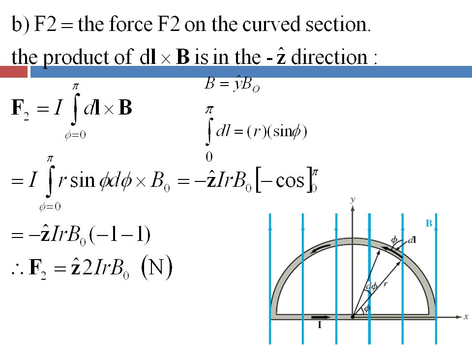
Example 1 The semicircular conductor shown carries a current I. The closed circuit is exposed to a uniform magnetic field Determine (a) the magnetic force F1 on the straight section of the wire and (b) the force F2 on the curved section.
 the magnetic force F1 on the straight section of the wire and. (b) the force F2 on the curved section.")
16
Solution to Example 1 a) the magnetic force F1 on the straight section of the wire
 the magnetic force F1 on the straight section of the wire")
18
Torque d = moment arm F = force T = torque

19
Magnetic Torque on Current Loop
No forces on arms 2 and 4 ( because I and B are parallel, or anti-parallel) Magnetic torque: Area of Loop
 Magnetic torque: Area of Loop.")
20
Inclined Loop For a loop with N turns and whose surface normal is at angle theta relative to B direction:

21
The Biot–Savart’s Law where:
The Biot–Savart law is used to compute the magnetic field generated by a steady current, i.e. a continual flow of charges, for example through a wire Biot–Savart’s law states that: where: dH = differential magnetic field dl = differential length

22
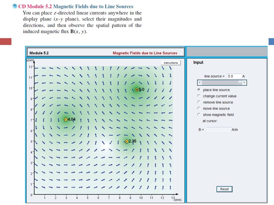
Biot-Savart Law Magnetic field induced by a differential current:
For the entire length:

23
Magnetic Field due to Current Densities

24
Example 2 Determine the magnetic field at the apex O of the pie-shaped loop as shown. Ignore the contributions to the field due to the current in the small arcs near O.

25
? = -dl For segment AC, dl is in φ direction,
O A C O A C ? For segment AC, dl is in φ direction, Using Biot- Savart’s law:

26
Example 5-2: Magnetic Field of Linear Conductor
Cont.

27
Example 5-2: Magnetic Field of Linear Conductor

28
Magnetic Field of Long Conductor

30
Example 5-3: Magnetic Field of a Loop
Magnitude of field due to dl is dH is in the r–z plane , and therefore it has components dHr and dHz z-components of the magnetic fields due to dl and dl’ add because they are in the same direction, but their r-components cancel Hence for element dl: Cont.

31
Example 5-3:Magnetic Field of a Loop (cont.)
For the entire loop:

32
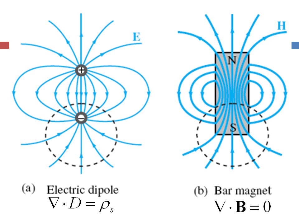
Magnetic Dipole Because a circular loop exhibits a magnetic field pattern similar to the electric field of an electric dipole, it is called a magnetic dipole

33
Forces on Parallel Conductors
Parallel wires attract if their currents are in the same direction, and repel if currents are in opposite directions

34
Gauss’s Law for Magnetism
Gauss’s law for magnetism states that: Magnetic field lines always form continuous closed loops.

36
Ampère’s Law

37
Ampere’s law for magnetism
Ampere’s law states that: true for an infinite length of conductor H C, +aø dl true for an infinite length of conductor I, +az r

38
Internal Magnetic Field of Long Conductor
For r < a Cont.

39
External Magnetic Field of Long Conductor
For r > a

40
Magnetic Field of Toroid
Applying Ampere’s law over contour C: Ampere’s law states that the line integral of H around a closed contour C is equal to the current traversing the surface bounded by the contour. The magnetic field outside the toroid is zero. Why?

41
Magnetic Flux The amount of magnetic flux, φ in Webers from magnetic field passing through a surface is found in a manner analogous to finding electric flux:

42
Example 4 An infinite length coaxial cable with inner conductor radius of 0.01m and outer conductor radius of 0.05m carrying a current of 2.5A exists along the z axis in the + az direction. Find the flux passing through the region between two conductors with height of 2 m in free space.

43
Solution to Example 4 inner conductor radius = r1 0.01m
outer conductor radius = r2 0.05m current of 2.5A (in the +az direction) Flux radius = 2m Iaz=2.5A z aø Flux,z xy r1 r2
 Flux radius = 2m. Iaz=2.5A. z. aø. Flux,z. xy. r1. r2.")
44
Solution to Example 4 where dS is in the aø direction. So, Therefore,

45
Magnetic Vector Potential A
Electrostatics Magnetostatics

46
Vector Magnetic Potential
For any vector of vector magnetic potential A: We are able to derive: Vector Poisson’s equation is given as: where

47
Magnetic Properties of Materials
Magnetization in a material is associated with atomic current loops generated by two principal mechanisms: Orbital motions of the electrons around the nucleus, i.e orbital magnetic moment, mo Electron spin about its own axis, i.e spin magnetic moment, ms

48
Magnetic Properties of Materials

49
Magnetic Permeability
Magnetization vector M is defined as where = magnetic susceptibility (dimensionless) Magnetic permeability is defined as: and to define the magnetic properties in term of relative permeability is defined as:
 Magnetic permeability is defined as: and to define the magnetic properties in term of relative permeability is defined as:")
50
Magnetic Materials - Diamagnetic
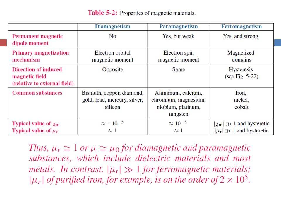
metals have a very weak and negative susceptibility ( ) to magnetic field slightly repelled by a magnetic field and the material does not retain the magnetic properties when the external field is removed Most elements in the periodic table, including copper, silver, and gold, are diamagnetic.
 to magnetic field. slightly repelled by a magnetic field and the material does not retain the magnetic properties when the external field is removed. Most elements in the periodic table, including copper, silver, and gold, are diamagnetic.")
51
Magnetic Materials - Paramagnetic
Paramagnetic materials have a small and positive susceptibilities to magnetic fields. slightly attracted by a magnetic field and the material does not retain the magnetic properties when the external field is removed. Paramagnetic materials include magnesium, molybdenum, lithium, and tantalum.

52
Magnetic Materials – Diamagnetic, Paramagnetic
However, the absolute susceptibilities value of both materials is in the order Thus, can be ignored. Hence, we have Magnetic permeability: Diamagnetic and paramagnetic materials include dielectric materials and most metals.

53
Magnetic Materials – Ferromagnetic Materials
Ferromagnetic materials is characterized by magnetized domain - a microscopic region within which the magnetic moments of all its atoms are aligned parallel to each other. Hysteresis – “to lag behind”. It determines how easy/hard for a magnetic material to be magnetized and demagnetized.

54
Process of Magnetic Hysteresis
material is magnetized and can serve as permanent magnet! B material is demagnetize

55
Magnetic Hysteresis of Ferromagnetic Materials
Comparison of hysteresis curves for (a) a hard and (b) a soft ferromagnetic material is shown. Hard magnetic material- cannot be easily magnetized & demagnetized by an external magnetic field. Soft magnetic material – easily magnetized & demagnetized.
 a hard and (b) a soft ferromagnetic material is shown. Hard magnetic material- cannot be. easily magnetized & demagnetized by an external magnetic field. Soft magnetic material – easily. magnetized & demagnetized.")
56
Magnetic Hysteresis

58
Boundary Conditions

59
Magnetic boundary conditions
Boundary condition related to normal components of the electric field; By analogy, application of Gauss’s law for magnetism, we get first boundary condition: Since , For linear, isotropic media, the first boundary condition which is related to H;

60
z xy By applying Ampere’s law

61
Magnetic boundary conditions
The result is generalized to a vector form: Where However, surface currents can exist only on the surfaces of perfect conductors and perfect superconductors (infinite conductivities). Hence, at the interface between media with finite conductivities, Js=0. Thus:
. Hence, at the interface between media with finite conductivities, Js=0. Thus:")
62
Example xy (plane)
")
63
Solution: H1t = H2t thus, H2t = 6ax + 2ay Hn1 = 3az, but, Hn2 = ??
6000μ0(3az) = 3000 μ0(Hn2) Hn2 = 6az thus, H2 =6ax + 2ay + 6az μr1 = 6000 ; μr2 = 3000 ;
 = 3000 μ0(Hn2) Hn2 = 6az. thus, H2 =6ax + 2ay + 6az. μr1 = 6000 ; μr2 = 3000 ;")
64
Inductance An inductor is the magnetic analogue of an electrical capacitor. Capacitor can store electric energy in the electric field present in the medium between its conducting surfaces. Inductor can store magnetic energy in the volume comprising the inductors.

65
calculate magnetic field in solenoid Calculate Magnetic Energy
Mutual inductance: produced by magnetic coupling between two different conducting structures. Calculate Magnetic Energy Self inductance: is the ratio of the magnetic flux linkage, Λ to the current I flowing through the structure. INDUCTANCE store magnetic energy

66
Solenoid Inside the solenoid:

67
Inductance Example of an inductor is a solenoid - a coil consisting of multiple turns of wire wound in a helical geometry around a cylindrical core.

68
Magnetic Field in a Solenoid
For one cross section of solenoid, When l >a, θ1≈−90° and θ2≈90°, Where, N=nl =total number of turns over the length l

69
(The ratio of the magnetic flux to the current)
Self Inductance The self-inductance of a circuit is used to describe the reaction of the circuit to a changing current in the circuit, (The ratio of the magnetic flux to the current)
")
70
Self Inductance Self-inductance of any conducting structure is the ratio of the magnetic flux linkage, Λ to the current I flowing through the structure. Magnetic flux linkage, Λ is the total magnetic flux linking a given conducting structure.

71
Self Inductance Magnetic flux, linking a surface S is given by:
In a solenoid with uniform magnetic field, the flux linking a single loop is:

72
Self Inductance – magnetic flux in solenoid

73
Self Inductance Magnetic flux, linking a surface S is given by:
In a solenoid with uniform magnetic field, the flux linking a single loop is:

74
Self Inductance For a solenoid: For two conductor configuration:

75
Self Inductance for a solenoid
Thus,

76
Mutual Inductance Mutual inductance – produced by magnetic coupling between two different conducting structures.

77
Mutual Inductance Magnetic field B1 generated by current I1 results in a flux Φ12 through loop 2: If loop 2 consists of N2 turns all coupled by B1 in exactly the same way, the total magnetic flux linkage through loop 2 due to B1 is:

78
Mutual Inductance Hence, the mutual inductance:

79
Inductance Magnetic Flux Flux Linkage Inductance Solenoid

80
Magnetic Energy Consider an inductor with an inductance L connected to a current source. The current I flowing through the inductor is increased from zero to a final value I. The energy expended in building up the current in the inductor: i.e the magnetic energy stored in the inductor

81
Magnetic Energy Magnetic energy density (for solenoid):
i.e magnetic energy per unit volume Magnetic energy in magnetic field:

82
Example 5-7: Inductance of Coaxial Cable
The magnetic field in the region S between the two conductors is approximately Total magnetic flux through S: Inductance per unit length:

83
Magnetic Energy Density
Magnetic field in the insulating material is The magnetic energy stored in the coaxial cable is

84
Summary

Similar presentations


.>")


>")
 shows the magnetic field lines surrounding a current loop Figure (b) shows the field lines in the iron filings.>")
