Download presentation
Presentation is loading. Please wait.

1
FETS Ion Source Installation progress UKNF Meeting Trinity College, September 15-16 2008 Dan Faircloth, Scott Lawrie, Alan Letchford, Christoph Gabor, Phil Wise, Mark Whitehead, Trevor Wood, Mike Perkins, Mick Bates, Pete Savage, David Lee, Juergen Pozimski, Rafael Enparantza Faircloth

2
Mounting Flange Negative Ion Beam Mica Penning Pole Pieces 10mm Aperture Plate Water Cooling Channels Source Body Air Cooling Channels Ceramic Spacer Copper Spacer Cathode Hollow Anode Discharge Region Extraction Electrode

3
+ Pulsed Extraction Power Supply - Platform Ground Extraction Electrode Aperture Plate Extraction Electrode, Coldbox and Sector Magnet all Pulsed Coldbox 90 Sector Magnet Extraction Gap Post Extraction Acceleration Gap +- 40 MΩ40 kΩ Protection Electrode FETS Source Schematic Platform DC Power Supply Laboratory Ground + - Ground Plane Suppression Electrode Suppressor Power Supply H - Beam

4
FETS Source

5
70 kV Load-Bearing Insulator Electrostatic Finite Element Modelling Mechanical

6
Post Extraction Acceleration Assembly Spacer Pumping Holes Toriod Housing Toriod Protection Electrode Suppression Electrode Ground Electrode Magnetic Shielding

7
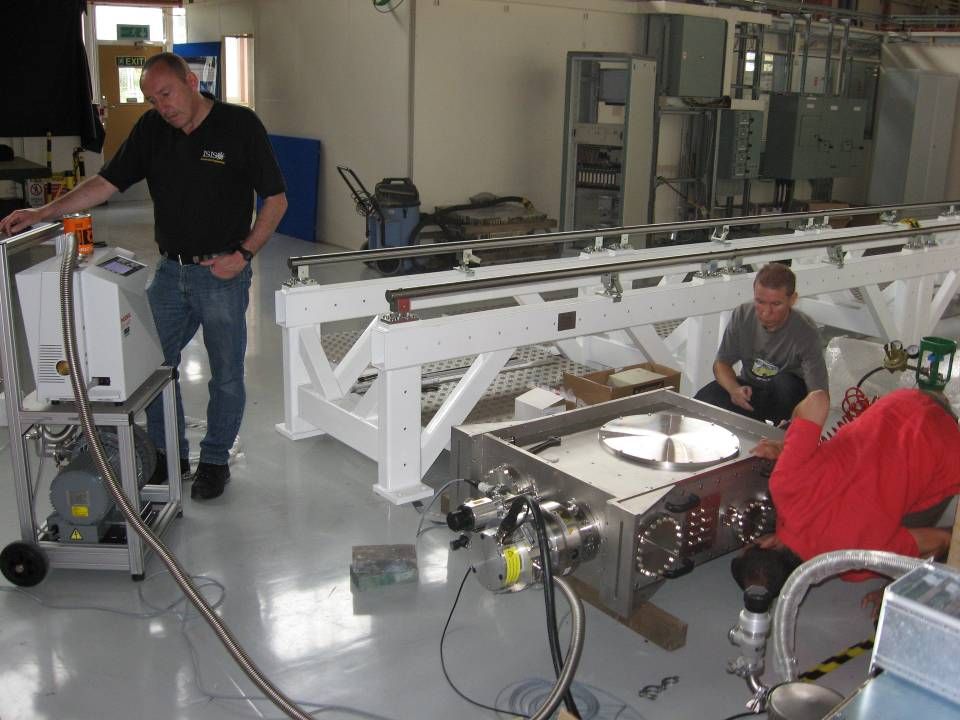
Solenoid Rail system 4 x Turbovac MAG W830 Turbovac 340M Post Acceleration Electrode Assembly 70 kV Insulator Ion source flange CF160 vacuum port Door chassis Mirror motor cradle 90 0 magnets and faraday cup KF40 laser port CF100 cable port Source Vacuum Box

8
Key Design Modifications Improve Cooling: Increase discharge length from 500 μs to 2 ms

9
600 520 440 360 280 200 Steady State Solution Thermal Modelling 3D Finite Element Model of the Ion Source using ALGOR. 1000μs duty Cathode Surface Anode Surface ΔT= 73 ºC ΔT= 39 ºC Transient Solution Computational Fluid Dynamic Cooling Calculation Improve cooling to work at longer duty cycles.

10
Key Design Modifications Improve Cooling: Increase discharge length from 500 μs to 2 ms Increase Extraction Aperture Size by 33% : 10 mm x 0.6 mm to 10 mm x 0.8 mm.

11
Increase Aperture Width Increase width by 33% from 0.6 mm to 0.8 mm Achieve 78 mA 0.5 ms 50 Hz Slit is 10 mm long

12
Key Design Modifications Improve Cooling: Increase discharge length from 500 μs to 2 ms Extraction Electrode : Convert from open jaw design to terminated pierce. Increase Extraction Aperture Size by 33% : 10 mm x 0.6 mm to 10 mm x 0.8 mm.

13
Modified extract electrodes to improve the beam emittance. StandardTerminated Pierce

14
Key Design Modifications Improve Cooling: Increase discharge length from 500 μs to 2 ms Extraction Electrode : Convert from open jaw design to terminated pierce. Extraction Voltage : Increase from 17 kV to 25 kV. Increase Extraction Aperture Size by 33% : 10 mm x 0.6 mm to 10 mm x 0.8 mm.

15
Increase Extraction Voltage Post Gap ?

16
Key Design Modifications Improve Cooling: Increase discharge length from 500 μs to 2 ms Extraction Electrode : Convert from open jaw design to terminated pierce. Sector Magnet: Increase good field region and change field gradient index. Extraction Voltage : Increase from 17 kV to 25 kV. Increase Extraction Aperture Size by 33% : 10 mm x 0.6 mm to 10 mm x 0.8 mm.

17
Sector Magnet Pole Pieces Magnetic Field Gradient Index, n Scott Lawrie n =1.4 n =1.0n =0.8 STANDARD ISIS POLES

18
Development Rig Results n = 1.4 Old Test new pole pieces: ε V = 0.40 rms norm π mm mRad ε H = 0.68 rms norm π mm mRad n = 1.4 Large Good Field 55 mA ε H = 0.79 rms norm π mm mRad ε V = 0.33 π mm mRad ε V = 0.30 rms norm π mm mRad n = 1.0 55 mA

19
Key Design Modifications Improve Cooling: Increase discharge length from 500 μs to 2 ms Extraction Electrode : Convert from open jaw design to terminated pierce. Sector Magnet: Increase good field region and change field gradient index. Increase Post Extraction Acceleration Field : 0.33 kVmm -1 to 9 kVmm -1 Extraction Voltage : Increase from 17 kV to 25 kV. Increase Extraction Aperture Size by 33% : 10 mm x 0.6 mm to 10 mm x 0.8 mm.

20
Emittance Growth Christoph Gabor

21
Decrease Post Acceleration Gap ε H = 0.90 norm rms π mm mRad ε V = 0.84 norm rms π mm mRad 55 mm Post gap ε H = 0.68 Norm rms π mm mRad ε V = 0.43 Norm rms π mm mRad 2 mm Post gap

22
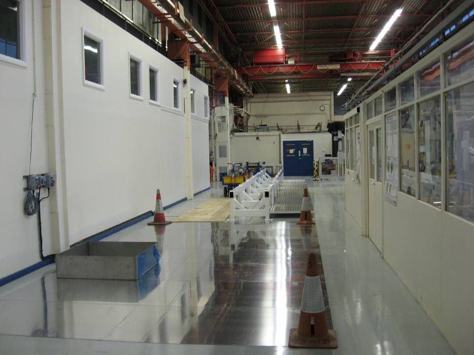
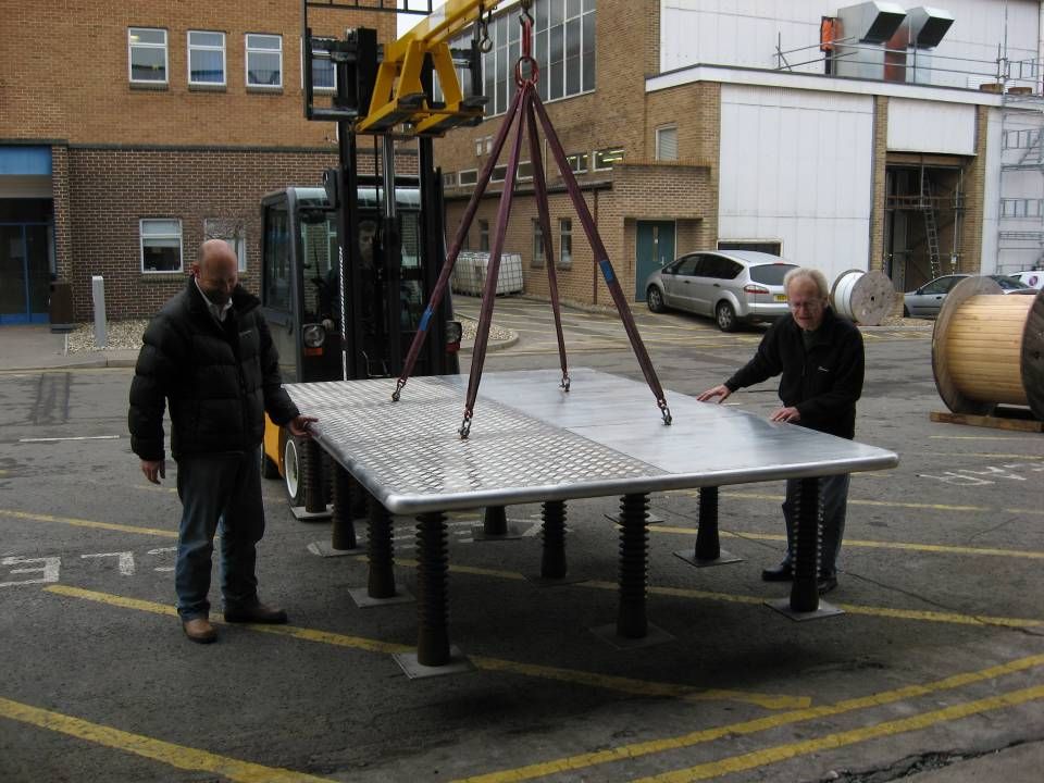
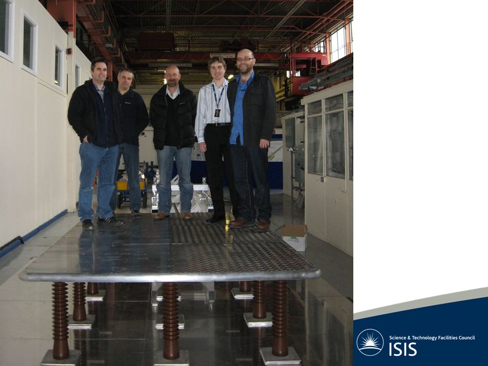
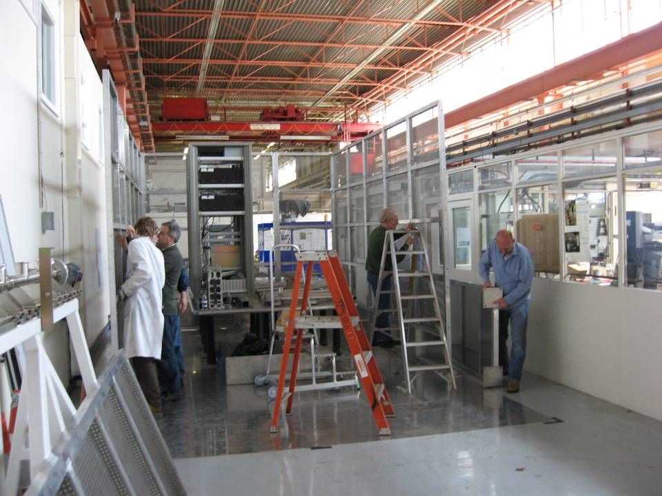
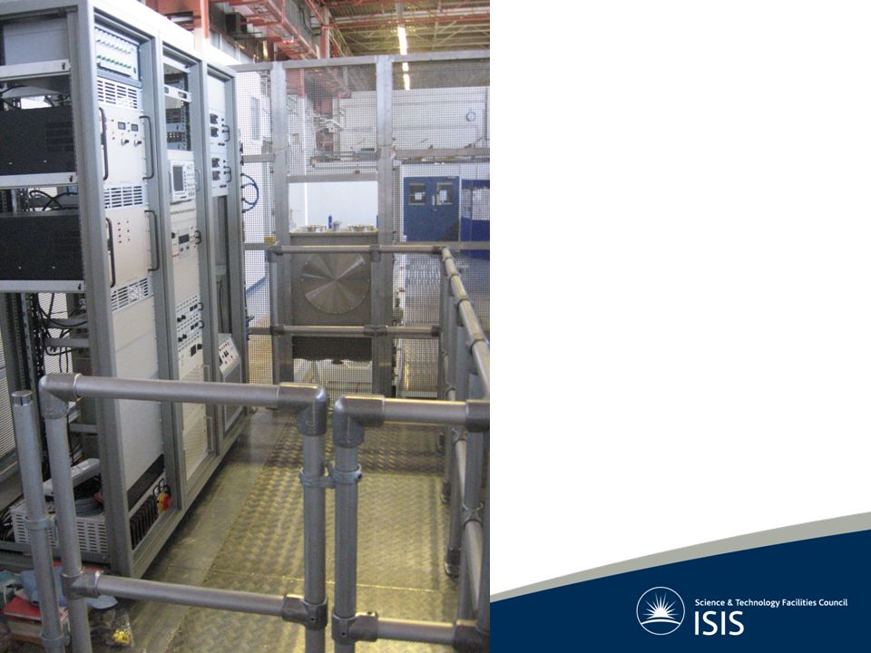
FETS Installation 70 kV HV Platform Construction HV Cage Construction

29
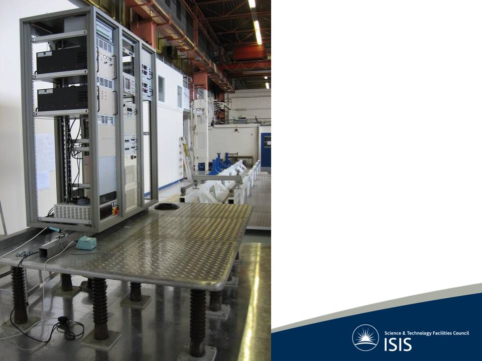
25 kV 2 ms @ 50 Hz Pulsed Extraction Power Supply Power Distribution Control Fibres Monitoring Breakout Scope Analogue Fibre Link Discharge Power Supply Temperature Crate Temperature Crate Extraction Power Supply Discharge Power Supply Gas Controller Control Crate Magnet Power Supply Gas and Water Manifold ION SOURCE Churchill Chiller Fridge Unit Ancillary Equipment Layout

30
70 kV DC Platform Supply 1 μF Capacitor

33
Outstanding Tasks Alignment 25 kV pulsed extraction power supply

34
Summary Table ISISFETS Output Current50 mA60-70 mA Pulse Length250 μs1.5 – 2 ms Output Energy35 keV65 keV Extraction Voltage17 kV25 kV Post Acceleration Voltage18 kV40 kV Post Acceleration Gap55 mm3 – 9 mm Emittance0.9 rms norm mm mRads 0.5 rms norm mm mRads First Beam - Autumn 2008

35
Thank you for your attention. Questions? Faircloth

Similar presentations


 Dan Bollinger (FNAL)>")


, M. Pivi, W. Lanfa (SLAC) 2008/3/3-61TLC08 Sendai.>")
 M. Yamamoto, T. Miyajima, Y. Honda KEK H. Iijima, M.>")
, Japan>")


