Download presentation
Presentation is loading. Please wait.

1
EV-EMCU Electric Vehicle - Economy Mode Control Unit Shauntice Diaz Chris Chadman Vanessa Baltacioglu Group 4

2
Goals & Objectives Extend range by implementing economy-mode Minimize power usage by attenuating acceleration to an optimum value Use several microcontrollers to allow data recording, vehicle safety, and to calculate optimum power usage Take in user’s inputs such as current, State of charge, RPMs, MPH, temperature, and acceleration USB storage or SD card Intelligent driving system DOT Approved

3
Specifications & Requirements To increase range by 5-10% 12V auxiliary power supply 144V vehicle power supply 7 electrical sensors 5v power supply for microcontrollers Data recording for 90 minutes C language

4
Overall Block Diagram

5
Physics Relate Electric Power to Mechanical Power Find Minimum Acceleration for Economy Mode Minimize Electric Power Loss through Heat by Limiting Current / Acceleration Find Power Needed for Acceleration P in = VI in = 220.46v + 0.87v 3 + vma + vmg*SIN(θ) P r P a Current as a Function of Acceleration and Velocity I = [220.46v + 34.32v 2 + 13,789v*sinθ + 1406va] / V Max Current ~ 350 A; Attenuate Potentiometer as % of I Test Values
![Physics Relate Electric Power to Mechanical Power Find Minimum Acceleration for Economy Mode Minimize Electric Power Loss through Heat by Limiting Current / Acceleration Find Power Needed for Acceleration P in = VI in = v v 3 + vma + vmg*SIN(θ) P r P a Current as a Function of Acceleration and Velocity I = [220.46v v ,789v*sinθ va] / V Max Current ~ 350 A; Attenuate Potentiometer as % of I Test Values](http://images.slideplayer.com/33/7052462/slides/slide_5.jpg "Physics Relate Electric Power to Mechanical Power Find Minimum Acceleration for Economy Mode Minimize Electric Power Loss through Heat by Limiting Current / Acceleration Find Power Needed for Acceleration P in = VI in = v v 3 + vma + vmg*SIN(θ) P r P a Current as a Function of Acceleration and Velocity I = [220.46v v ,789v*sinθ va] / V Max Current ~ 350 A; Attenuate Potentiometer as % of I Test Values")
6
Physics

7
Peukert’s Law : t = Time of Discharge H = Rated discharge Time (hrs) C = Rated Capacity @ Discharge Time t I = Discharge Current K = Peukert’s Constant
 C = Rated Discharge Time t I = Discharge Current K = Peukert’s Constant")
8
Physics Internal Battery Resistance ▫ EV12A- AGM; R i = 3.2mΩ ▫ Full Power VI = 144V*350A = 50.4 kW ▫ Power Loss @ 350A = 4.7 kW; 9.5% ▫ Temperature Effects

9
Sensors Speed ▫ 0 to 70 miles per hour ▫ Pulse Width Modulation RPM ▫ 0 to 5000 Revolutions Per Minute ▫ Pulse Width Modulation Current ▫ -500 to 500 Amps ▫ Analog State Of Charge ▫ 10.5volts – 13. 2 Volts ( 0 to 100%) ▫ Analog Battery Temperature ▫ -40 ̊ C to 60 ̊ C ▫ Analog Potentiometer ▫ 0-12Volts ▫ Analog Accelerometer ▫ ± 2g’s (horizontal) ▫ Analog
 ▫ Analog Battery Temperature ▫ -40 ̊ C to 60 ̊ C ▫ Analog Potentiometer ▫ 0-12Volts ▫ Analog Accelerometer ▫ ± 2g’s (horizontal) ▫ Analog.")
10
Speed Sensor ’94 Transmission, ’04 Vehicle Electrical Sensor added PWM Measured from Transmission or Rear Diff (ABS)
")
11
RPM sensor Measured from motor using Hall Effect Recommend by NetGain Operates under 12V(DC) power supply 2.2K integrated resistor Pulse width modulated output 5.5 mA
 power supply 2.2K integrated resistor Pulse width modulated output 5.5 mA")
12
Current sensor Hall Effect current sensor From EV source recommended by NetGain Series connection to 144V system Measures the range of ±500 Amps Output signal of 1.5 to 4.5 Volts Linearly related

13
State of Charge PakTrakr 600EV Measures current, SOC, and battery Temp RS-232 output Expensive

14
Accelerometer Dimensions Engineering Had specs that met the requirements Simple design ±2g to the velocity plane of the vehicle Internal 3.3v voltage regulator Output in volts [ X OUT – (V CC / 2)] / sensitivity = acceleration in the x direction
![Accelerometer Dimensions Engineering Had specs that met the requirements Simple design ±2g to the velocity plane of the vehicle Internal 3.3v voltage regulator Output in volts [ X OUT – (V CC / 2)] / sensitivity = acceleration in the x direction](http://images.slideplayer.com/33/7052462/slides/slide_14.jpg "Accelerometer Dimensions Engineering Had specs that met the requirements Simple design ±2g to the velocity plane of the vehicle Internal 3.3v voltage regulator Output in volts [ X OUT – (V CC / 2)] / sensitivity = acceleration in the x direction")
15
Potentiometer 0-12v controlled by user Step down to 0-5v Previously installed Controls the motor controller Will adjust output of potbox according to power microcontroller

16
Microcontroller PIC16F886 Microchip Technologies 28 Pin DIP 14 10 bit A/D Converters 2 8 bit Timers 2 Analog Comparators 2 Output 10bit PWM Designed for Intelligent Driving System

17
Development Board 28 Pin LIN Demo Board, Microchip Technologies For Use with Most 28 Pin DIP PIC MCU ’ s Programmed with PICkit 2 Micorcontroller Programmer

18
Sensor Microcontroller 5 analog inputs (current, accelerometer, potentiometer, Temperature, and state of Charge ) Two PWM (speed, rpm) Reset Heartbeat 7 outputs to power and data microcontrollers
 Two PWM (speed, rpm) Reset Heartbeat 7 outputs to power and data microcontrollers")
19
Power Controller 7 inputs from sensor microcontroller Heartbeat Computes optimum acceleration ▫ Test Data ▫ Peukert’s Law ▫ Battery Resistance Outputs to safety microcontroller

20
Safety Microcontroller 3 Inputs: Potentiometer, Power MCU, and Reset 3 Outputs: Motor controller, WDT, and Data Acts like typical a comparator Prevents runaway acceleration

21
Data Microcontroller 7 inputs from sensor controller 1 from Power, 1 from safety 1 Reset,1 heartbeat 1 Output from USBwiz to microcontroller ▫ 3 ways UART I2C SPI

22
Data Microcontroller: USBWiz Fully assembled and tested 2 USB and SD connectors Single 3.3 V regulator Ready for 32 Khz crystal Complete ‘C’ source code library Support fat file system Easy connection with PIC and AVR 40 to 50 mA, power consumption 5v tolerant I/O pins -40 °C to + 85°C temperature operation range Lead free.

23
WatchDog Timer Used to monitor and minimize errors Timeout period and reset period Two types ▫ Hardware (external) ▫ Software (internal)
 ▫ Software (internal)")
24
Internal Watchdog Timer Positives ▫ Cost is essentially zero ▫ Can save debugging information ▫ Convenient ▫ Can modify timeout ▫ Can vary less with temperature Negatives ▫ Almost all can be disabled by software

25
External Watchdog Timer Positives ▫ Cant be disable accidentally ▫ Separate clock source ▫ Min/Max timeout period ▫ Reset can connect to other system ▫Timeout period is adjustable Negatives ▫ Cost ▫ Timeout period varies ▫ One I/O line ▫ Timeout must be calculated (both high and low speed)
")
26
Our decision External Capacitor adjustable ▫ Voltage monitoring ▫ 1.565v to 5v ▫ Watchdog timeout ▫ 700ms to 70s (100pF to 100nF capacitor) ▫ Reset timeout ▫ Preset, or 0.5 ms to 5s by capacitor
 ▫ Reset timeout ▫ Preset, or 0.5 ms to 5s by capacitor")
27
Original Goals & Specifications Solar assisted EV conversion Range of 60+ miles User friendly display (touch screen) DOT approved Wireless applications Regenerative braking Power steering
 DOT approved Wireless applications Regenerative braking Power steering")
28
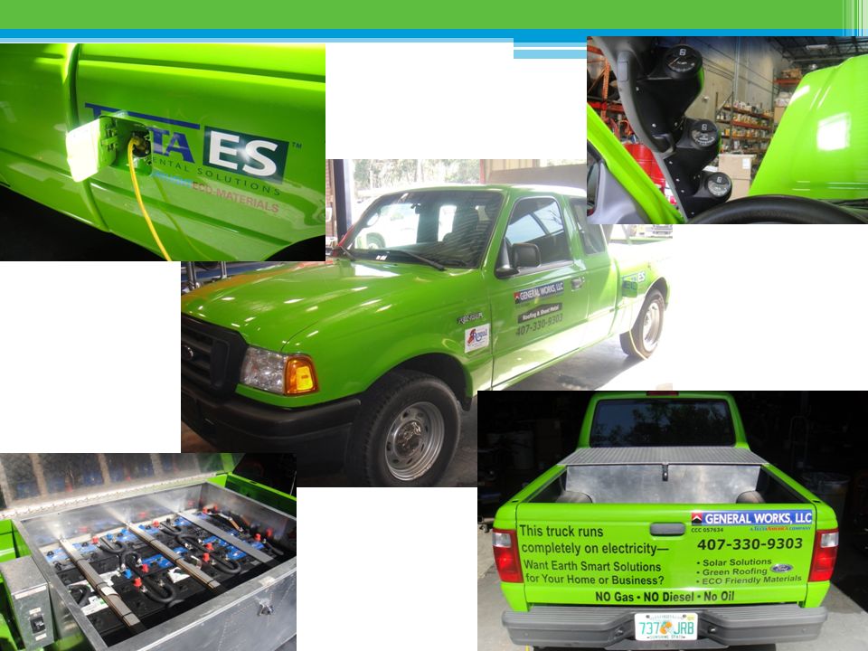
Changes From Original Design Batteries ▫ 12 12v swap for 24 6v (cost $2400) ▫ Battery weight from 1074 to 1488 pounds (38.5% increase) ▫ Not much engineering design required ▫ Main benefit would be longer battery life Touch Screen Display ▫ Lost computer engineering student in our group who was working on this part Solar Panels ▫ Tecta America (who installs solar roof panels) advised us against using solar panels ▫ Not enough surface area to produce enough energy to be worthwhile
 ▫ Battery weight from 1074 to 1488 pounds (38.5% increase) ▫ Not much engineering design required ▫ Main benefit would be longer battery life Touch Screen Display ▫ Lost computer engineering student in our group who was working on this part Solar Panels ▫ Tecta America (who installs solar roof panels) advised us against using solar panels ▫ Not enough surface area to produce enough energy to be worthwhile")
29
Budget Electric truck from Tecta America - FREE Eagle PCB - $50 Microcontrollers – QTY 10 @ $2 each = $20 Development board – $40 Op-amps – QTY 20 @ $0.38 = $8.00 USBWIZ - $50 Speed Sensor – $49 RPM sensor – $99 Hall Effect current sensor – $49 PakTrakr 600 EV sensor (Battery Temp and S.O.C.) – $150 Extra PakTrakr remote - $70 Accelerometer – $23 WatchDog Timer – QTY 15 @ $1.56 = $24 Soldering Iron with station (Amazon) – $50 Breadboard Kit (Amazon) – $25 Waterproof box – TBA (with final dimensions) Miscellaneous (wiring, bolts, tax, shipping, etc) - $100 Total Estimate: $807 Old total : $3500 (with batteries and touch screen display)
 – $150 Extra PakTrakr remote - $70 Accelerometer – $23 WatchDog Timer – QTY $1.56 = $24 Soldering Iron with station (Amazon) – $50 Breadboard Kit (Amazon) – $25 Waterproof box – TBA (with final dimensions) Miscellaneous (wiring, bolts, tax, shipping, etc) - $100 Total Estimate: $807 Old total : $3500 (with batteries and touch screen display)")
30
Progress

Similar presentations
 4 Line by 18 Character fully.>")
>")


: –Power.>")


 Group Leader: Tomas Mullins Communicator: Casey Liebl Webmaster: Shiya Liu Team Members: Andrew Gurik & Qiao.>")


