Download presentation
Presentation is loading. Please wait.

1
Physical Layer Issues - Transmission Media and Network Cabling
Hitesh lad

2
What is Cable? Transmission Media
Transmission medium is the physical path between the transmitter and receiver. It is the Transmission medium through which information usually moves from one network device to another. In some cases, a network will utilize only one type of cable, other networks will use a variety of cable types. Understanding the characteristics of different types of transmission media and how they relate to other aspects of a network is necessary for the development of a successful network.

4
Factors to Select Transmission Media
Data Rate and Bandwidth (BPS and Hz) Distance and Attenuation (meters, dB/km) Interference Characteristics Number of receivers (broadcast vs. point to point) Cost - Remember cabling is a long term investment!
 Distance and Attenuation (meters, dB/km) Interference Characteristics. Number of receivers (broadcast vs. point to point) Cost - Remember cabling is a long term investment!")
5
Transmission Impairments
Impairments exist in all forms of data transmission media Analog signal impairments result in random modifications that impair signal quality Digital signal impairments result in bit errors (1s and 0s transposed)
")
6
Types of Media Two major classes Conducted or guided media
use a conductor such as a wire or a fiber optic cable to move the signal from sender to receiver. Energy is confined to the medium and guided by it Wireless or unguided media use radio waves of different frequencies and do not need a wire or cable conductor to transmit signals Energy spreads out and is not confined

7
Media Sub-types Guided Media Unguided Media
Unshielded Twisted Pair (UTP) Cable Shielded Twisted Pair (STP) Cable Coaxial Cable Fiber Optic Cable Unguided Media Terrestrial microwave transmission Satellite transmission Broadcast radio Infrared
 Cable. Shielded Twisted Pair (STP) Cable. Coaxial Cable. Fiber Optic Cable. Unguided Media. Terrestrial microwave transmission. Satellite transmission. Broadcast radio. Infrared.")
8
Twisted Pair Wires Consists of two insulated copper wires arranged in a regular spiral pattern to minimize the electromagnetic interference between adjacent pairs Often used at customer facilities and also over distances to carry voice as well as data communications Low frequency transmission medium Two varieties STP (shielded twisted pair) the pair is wrapped with metallic foil or braid to insulate the pair from electromagnetic interference UTP (unshielded twisted pair) each wire is insulated with plastic wrap, but the pair is encased in an outer covering
 the pair is wrapped with metallic foil or braid to insulate the pair from electromagnetic interference. UTP (unshielded twisted pair) each wire is insulated with plastic wrap, but the pair is encased in an outer covering.")
9
Twisted Pair One difference between the different categories of UTP is the tightness of the twisting of the copper pairs. The tighter the twisting, the higher the supported transmission rate and the greater the cost per foot. Each pair is twisted with a different number of twists per inch to help eliminate interference from adjacent pairs and other electrical devices.

10
Categories of Unshielded Twisted Pair
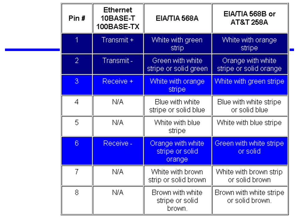
The EIA/TIA (Electronic Industry Association/Telecommunication Industry Association) has established standards of UTP and rated five categories of wire. Type Use Category 1 Voice Only (Telephone Wire) Category 2 Data to 4 Mbps (LocalTalk) Category 3 Data to 10 Mbps (Ethernet) Category 4 Data to 20 Mbps (16 Mbps Token Ring) Category 5 Data to 100 Mbps (Fast Ethernet) Category 5e Data to 1000 Mbps (Gigabit Ethernet) Category 6 Data to 1000 Mbps (Gigabit Ethernet) Category 7 ?
 has established standards of UTP and rated five categories of wire. Type Use. Category 1 Voice Only (Telephone Wire) Category 2 Data to 4 Mbps (LocalTalk) Category 3 Data to 10 Mbps (Ethernet) Category 4 Data to 20 Mbps (16 Mbps Token Ring) Category 5 Data to 100 Mbps (Fast Ethernet) Category 5e Data to 1000 Mbps (Gigabit Ethernet) Category 6 Data to 1000 Mbps (Gigabit Ethernet) Category 7")
11
Benefits of UTP Disadvantages of UTP Inexpensive and readily available
Flexible and light weight Easy to work with and install Disadvantages of UTP Susceptibility to interference and noise Attenuation problem For analog, repeaters needed every 5-6km For digital, repeaters needed every 2-3km Relatively low bandwidth (3000Hz)
")
13
Twisted Pair - Applications
Telephone network Between house and local exchange (subscriber loop/local loop) Within buildings To private branch exchange (PBX) For local area networks (LAN) 10Mbps or 100Mbps or 1000 Mbps
 Within buildings. To private branch exchange (PBX) For local area networks (LAN) 10Mbps or 100Mbps or 1000 Mbps.")
14
Unshielded Twisted Pair Connector
The standard connector for unshielded twisted pair cabling is an RJ-45 connector. This is a plastic connector that looks like a large telephone-style connector (See figure). A slot allows the RJ-45 to be inserted only one way. RJ stands for Registered Jack, implying that the connector follows a standard borrowed from the telephone industry. This standard designates which wire goes with each pin inside the connector.
. A slot allows the RJ-45 to be inserted only one way. RJ stands for Registered Jack, implying that the connector follows a standard borrowed from the telephone industry. This standard designates which wire goes with each pin inside the connector.")
15
The RJ-45 Connector

16
Shielded Twisted Pair (STP) Cable
A disadvantage of UTP is that it may be susceptible to radio and electrical frequency interference (RFI, EFI). Shielded twisted pair (STP) is suitable for environments with electrical interference; however, the extra shielding can make the cables quite bulky. Shielded twisted pair is often used on networks using Token Ring topology. More expensive, harder to work with.
. Shielded twisted pair (STP) is suitable for environments with electrical interference; however, the extra shielding can make the cables quite bulky. Shielded twisted pair is often used on networks using Token Ring topology. More expensive, harder to work with.")
17
Shielded Twisted Pair (STP) Cable
 Cable")
18
Coaxial Cable Coaxial cabling has a single copper conductor at its center. A plastic layer provides insulation between the center conductor and a braided metal shield (See figure). The metal shield helps to block any outside interference from fluorescent lights, motors, and other computers. Both conductors share a common center axis, hence the term “co-axial”
. The metal shield helps to block any outside interference from fluorescent lights, motors, and other computers. Both conductors share a common center axis, hence the term co-axial")
19
Coax Layers outer jacket (polyethylene) shield (braided wire)
insulating material copper or aluminum conductor

20
Pros and Cons Coax Advantages Coax Disadvantages Higher bandwidth
400 to 600MHz up to 10,800 voice conversations Can be tapped easily (pros and cons) Much less susceptible to interference than twisted pair Greater cable lengths between network devices than twisted pair cable. Coax Disadvantages High attenuation rate makes it expensive over long distance Bulky - coaxial cabling is difficult to install
 Much less susceptible to interference than twisted pair. Greater cable lengths between network devices than twisted pair cable. Coax Disadvantages. High attenuation rate makes it expensive over long distance. Bulky - coaxial cabling is difficult to install.")
21
Coaxial Cable Applications
Most versatile medium Television distribution Ariel to TV Cable TV Long distance telephone transmission Can carry 10,000 voice calls simultaneously Being replaced by fiber optic Short distance computer systems links Local area networks

22
Types of Coaxial Cable Thin Coax Thick Coax
Thin coaxial cable is also referred to as thinnet. Thin coaxial cable is popular in linear bus networks. Thick Coax Thick coaxial cable is also referred to as thicknet. Thick coaxial cable has an extra protective plastic cover that helps keep moisture away from the center conductor. This makes thick coaxial a great choice when running longer lengths in a linear bus network. One disadvantage of thick coaxial is that it does not bend easily and is difficult to install.

23
Coaxial Cable Connectors
The most common type of connector used with coaxial cables is the Bayone-Neill-Concelman (BNC) connector (See figure). Different types of adapters are available for BNC connectors, including a T-connector, barrel connector, and terminator. Connectors on the cable are the weakest points in any network. To help avoid problems with your network, always use the BNC connectors that crimp, rather than screw, onto the cable.
 connector (See figure). Different types of adapters are available for BNC connectors, including a T-connector, barrel connector, and terminator. Connectors on the cable are the weakest points in any network. To help avoid problems with your network, always use the BNC connectors that crimp, rather than screw, onto the cable.")
24
Fiber Optic Cable Relatively new transmission medium used by telephone companies in place of long-distance trunk lines Also used by private companies in implementing local data communications networks Require a light source with injection laser diode (ILD) or light-emitting diodes (LED)
 or light-emitting diodes (LED)")
25
Fiber Optic Cable Fiber optic cabling consists of a center glass core surrounded by several layers of protective materials. It transmits light rather than electronic signals, eliminating the problem of electrical interference. This makes it ideal for certain environments that contain a large amount of electrical interference. It has also made it the standard for connecting networks between buildings, due to its immunity to the effects of moisture and lighting.

26
Fiber Optic Layers consists of three concentric sections
plastic jacket glass or plastic cladding fiber core

27
Optical Fiber

28
Armored Cable

29
Facts About Fiber Optic Cables
Outer insulating jacket is made of Teflon or PVC. Kevlar fiber helps to strengthen the cable and prevent breakage. A plastic coating is used to cushion the fiber center. Center (core) is made of glass or plastic fibers.
 is made of glass or plastic fibers.")
30
Fiber Optic Cable Fiber optic cable has the ability to transmit signals over much longer distances than coaxial and twisted pair. It also has the capability to carry information at vastly greater speeds. This capacity broadens communication possibilities to include services such as video conferencing and interactive services. The cost of fiber optic cabling is comparable to copper cabling; however, it is more difficult to install and modify.

31
Optical Fiber - Transmission Characteristics
Act as wave guide for 1014 to 1015 Hz Portions of infrared and visible spectrum Light Emitting Diode (LED) Cheaper Wider operating temp range Last longer Injection Laser Diode (ILD) More efficient Greater data rate Wavelength Division Multiplexing
 Cheaper. Wider operating temp range. Last longer. Injection Laser Diode (ILD) More efficient. Greater data rate. Wavelength Division Multiplexing.")
32
Fiber Optic Types Multimode step-index fiber
the reflective walls of the fiber move the light pulses to the receiver Multimode graded-index fiber acts to refract the light toward the center of the fiber by variations in the density Single mode fiber the light is guided down the center of an extremely narrow core

33
Optical Fiber Transmission Modes

34
Fiber Optic Signals fiber optic multimode step-index
graded-index fiber optic single mode

35
Pros and Cons Fiber Optic Advantages Fiber Optic Disadvantages
Greater capacity - data rates of hundreds of Gbps Smaller size and lighter weight Lower attenuation Electromagnetic isolation - immunity to environmental interference and highly secure due to tap difficulty and lack of signal radiation Greater repeater spacing - 10s of km at least Fiber Optic Disadvantages Expensive over short distance Requires highly skilled installers Adding additional nodes is difficult

36
Optical Fiber - Applications
Long-haul trunks Metropolitan trunks Rural exchange trunks Subscriber loops (FTTH, FTTC) LANs (generally backbone connections)
 LANs (generally backbone connections)")
37
Fiber Optic Connector The most common connector used with fiber optic cable is an ST connector. It is barrel shaped, similar to a BNC connector. A newer connector, the SC, is becoming more popular. It has a squared face and is easier to connect in a confined space.

38
Comparison of the Three Guided Media Types
1000 THz 1 THz 1 GHz 1 MHz Optical Fiber 1 kHz 0.1 3/8” Coaxial Cable 22-gauge Twisted Pair Frequency dB/km 1 10 100

39
Wireless (Unguided Media)
Transmission Transmission and reception are achieved by means of an antenna Directional transmitting antenna puts out focused beam transmitter and receiver must be aligned Omnidirectional signal spreads out in all directions can be received by many antennas

40
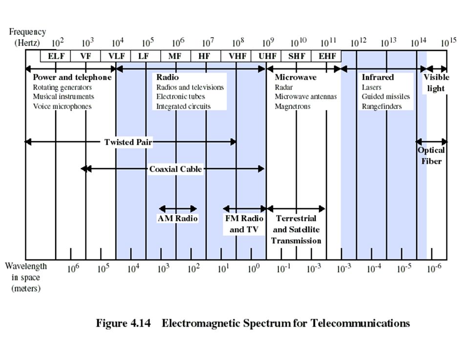
Wireless (Unguided Media) Frequencies
Three general ranges of frequencies 30MHz to 1GHz Broadcast radio Omnidirectional 2GHz to 40GHz microwave frequencies Microwave Highly directional Point to point Satellite 3 x 10¹¹ to 2 x 10¹⁴ Infrared

41
Propagation of Radio Frequencies

42
Propagation of Radio Frequencies (continued)
")
43
Terrestrial Microwave Transmission
Uses the radio frequency spectrum, commonly from 2 to 40 GHz Transmitter is a parabolic dish, mounted as high as possible Used by common carriers as well as by private networks Requires unobstructed line of sight between source and receiver Curvature of the earth requires stations (called repeaters) to be ~30 miles apart
 to be ~30 miles apart.")
44
Terrestrial Microwave Transmission
Distance between antennas: d = 7.14 (Kh)1/2 , d = distance in km, h is antenna height in meters, K = constant = 4/3
1/2 , d = distance in km, h is antenna height in meters, K = constant = 4/3.")
45
Terrestrial Microwave Applications
Long-haul telecommunications service for both voice and television transmission Short point-to-point links between buildings for closed-circuit TV or a data link between LANs

46
Terrestrial Microwave Communications

47
Pros and Cons Microwave Transmission Advantages
No cabling needed between sites Wide bandwidth Multi-channel transmissions Used for long haul or high capacity short haul Requires fewer amplifiers and repeaters Microwave Transmission Disadvantages Line of sight requirement Expensive towers and repeaters Subject to interference such as passing airplanes and rain Frequency bands are regulated

48
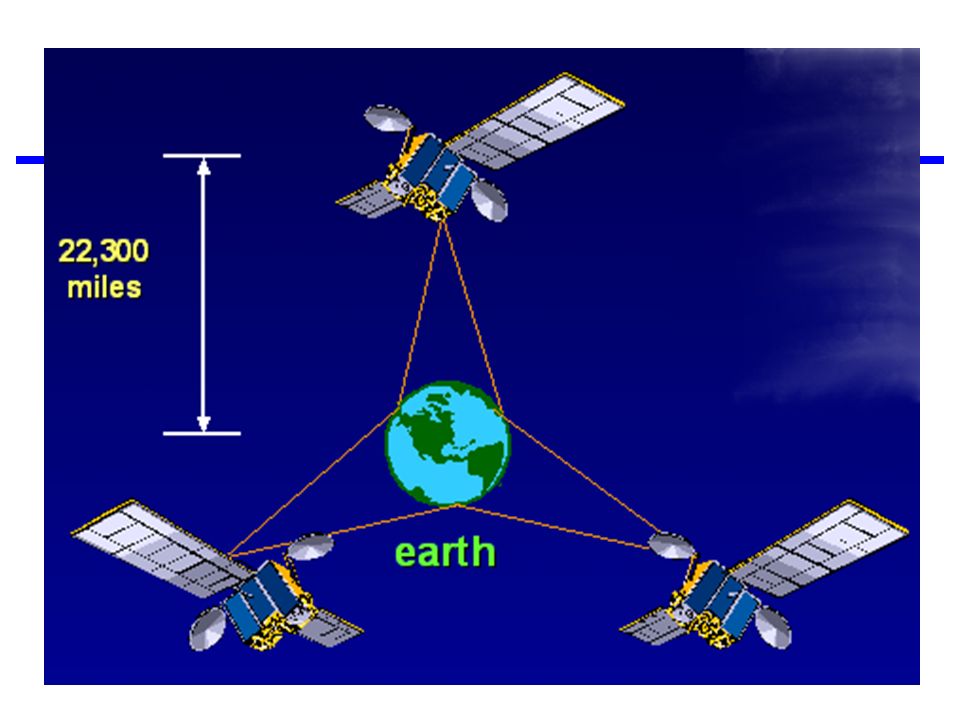
Satellite Microwave Transmission
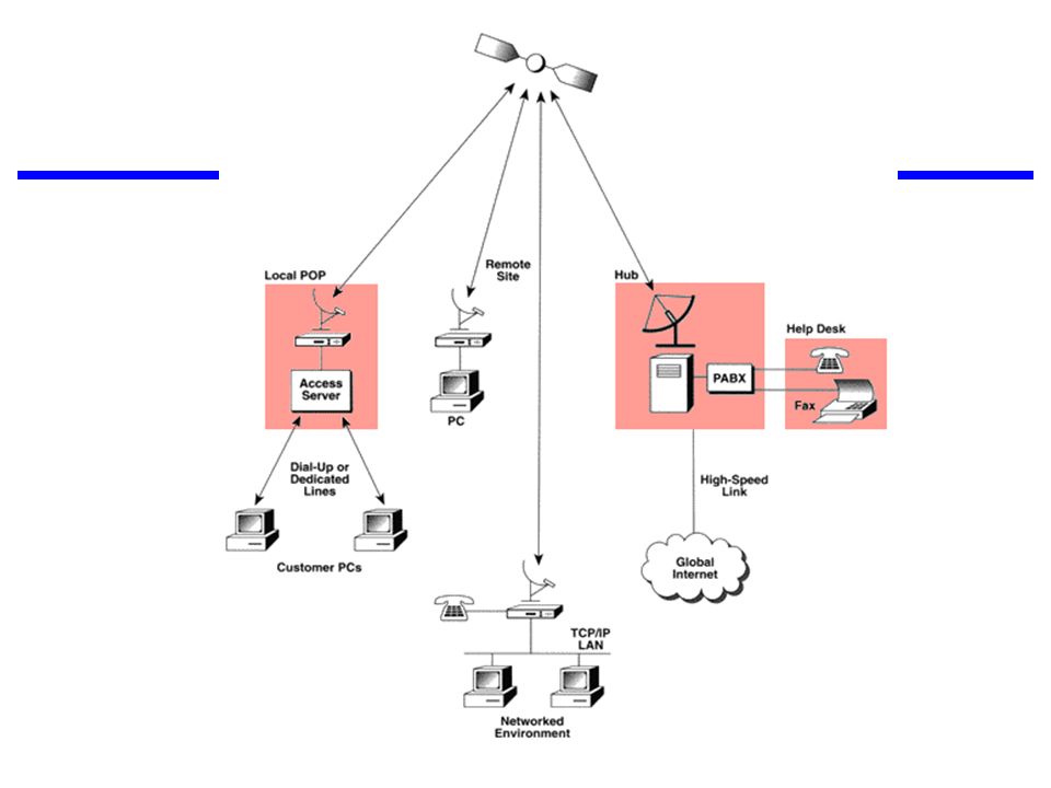
Satellite is a microwave relay station in space Can relay signals over long distances Geostationary satellites remain above the equator at a height of 22,300 miles (geosynchronous orbit) travel around the earth in exactly the time the earth takes to rotate Earth stations communicate by sending signals to the satellite on an uplink The satellite then repeats those signals on a downlink The broadcast nature of the downlink makes it attractive for services such as the distribution of television programming
 travel around the earth in exactly the time the earth takes to rotate. Earth stations communicate by sending signals to the satellite on an uplink. The satellite then repeats those signals on a downlink. The broadcast nature of the downlink makes it attractive for services such as the distribution of television programming.")
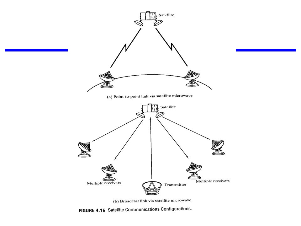
50
Satellite Transmission Process
transponder dish dish 22,300 miles uplink station downlink station

51
Satellite Transmission Applications
Television distribution a network provides programming from a central location direct broadcast satellite (DBS) Long-distance telephone transmission high-usage international trunks Private business networks
 Long-distance telephone transmission. high-usage international trunks. Private business networks.")
52
Principal Satellite Transmission Bands
C band: 4(downlink) - 6(uplink) GHz the first to be designated Ku band: 12(downlink) -14(uplink) GHz rain interference is the major problem Ka band: 19(downlink) - 29(uplink) GHz equipment needed to use the band is still very expensive
 - 6(uplink) GHz. the first to be designated. Ku band: 12(downlink) -14(uplink) GHz. rain interference is the major problem. Ka band: 19(downlink) - 29(uplink) GHz. equipment needed to use the band is still very expensive.")
53
Pros and Cons Satellite Advantages Satellite Disadvantages
Can reach a large geographical area High bandwidth Cheaper over long distances Satellite Disadvantages High initial cost Susceptible to noise and interference Propagation delay (0.25 sec) - requires sophisticated flow control
 - requires sophisticated flow control.")
56
Broadcast Radio Broadcast radio is omnidirectional
Covers 30MHz to 1 GHz (FM, UHF, VHF) Need line of sight. Ionosphere is transparent above 30MHz, hence no atmospheric reflection Advantages Less sensitive to attenuation from rainfall Disadvantages Multipath interference is significant
 Need line of sight. Ionosphere is transparent above 30MHz, hence no atmospheric reflection. Advantages. Less sensitive to attenuation from rainfall. Disadvantages. Multipath interference is significant.")
57
Infrared Transceivers operate with line of sight or reflection from light-colored surface Modulate noncoherent infrared light e.g. TV remote control, IRD port Advantages Does not penetrate walls - enhanced security No licensing of frequencies Disadvantages Operate on limited distances

58
Summary

59
The RS-232 Serial Interface and Ethernet 10/100BaseT

60
DB-25 Connectors DB-25/DB-9 is an old standard family of connectors which are used for various interface standards such as RS-232 (Serial), Parallel and SCSI interfaces. The DB-25 male and female connectors are shown in the figure. Please note the way the pins are numbered.
, Parallel and SCSI interfaces. The DB-25 male and female connectors are shown in the figure. Please note the way the pins are numbered.")
61
What is a Null Modem Cable?
A specially designed cable that allows you to connect two computers directly to each other via their communications ports (RS-232 ports). Null modems are particularly useful with portable computers because they enable the portable computer to exchange data with a larger system.
. Null modems are particularly useful with portable computers because they enable the portable computer to exchange data with a larger system.")
62
What is a Null Modem Cable?
The purpose of a null-modem cable is to permit two RS-232 "DTE" devices to communicate with each other without modems or other communication devices (i.e., "DCE"s) between them. To achieve this, the most obvious connection is that the TD signal of one device must be connected to the RD input of the other device (and vice versa). Also, however, many DTE devices use other RS-232 pins for out-of-band (i.e., "hardware") flow control. One of the most common schemes is for the DTE (the PC) to assert the RTS signal if it is ready to receive data (yes, it DOES sound backwards, but that's how it works), and for the DCE (the modem) to assert CTS when it is able to accept data. By connecting the RTS pin of one DTE to the CTS pin of the other DTE, we can simulate this handshake. Also, it is common convention for many DTE devices to assert the DTR signal when they are powered on, and for many DCE devices to assert the DSR signal when they are powered on, and to assert the CD signal when they are connected. By connecting the DTR signal of one DTE to both the CD and DSR inputs of the other DTE (and vice versa), we are able to trick each DTE into thinking that it is connected to a DCE that is powered up and online. As a general rule, the Ring Indicate (RI) signal is not passed through a null-modem connection
 between them. To achieve this, the most obvious connection is that the TD signal of one device must be connected to the RD input of the other device (and vice versa). Also, however, many DTE devices use other RS-232 pins for out-of-band (i.e., hardware ) flow control. One of the most common schemes is for the DTE (the PC) to assert the RTS signal if it is ready to receive data (yes, it DOES sound backwards, but that s how it works), and for the DCE (the modem) to assert CTS when it is able to accept data. By connecting the RTS pin of one DTE to the CTS pin of the other DTE, we can simulate this handshake. Also, it is common convention for many DTE devices to assert the DTR signal when they are powered on, and for many DCE devices to assert the DSR signal when they are powered on, and to assert the CD signal when they are connected. By connecting the DTR signal of one DTE to both the CD and DSR inputs of the other DTE (and vice versa), we are able to trick each DTE into thinking that it is connected to a DCE that is powered up and online. As a general rule, the Ring Indicate (RI) signal is not passed through a null-modem connection.")
63
DB-25 and DB-9 male and female connectors, as viewed from the pin side (not the solder side).
.")
64
DB-9 connectors on both ends

65
DB-25 connectors on both ends

66
DB-9 connector on one end, DB-25 on the other end

67
RS-232 Signals The RS-232 standard: DB-25 DCE DB-9 1 AA x
Protective Ground 2 TXD 3 BA I Transmitted Data RXD BB O Received Data 4 RTS 7 CA Request To Send 5 CTS 8 CB Clear To Send 6 DSR CC Data Set Ready GND AB Signal Ground CD CF Received Line Signal Detector 9 -- Reserved for data set testing 10 11 Unassigned 12 SCF Secndry Rcvd Line Signl Detctr 13 SCB Secondary Clear to Send 14 SBA Secondary Transmitted Data 15 DB Transmisn Signl Elemnt Timng 16 SBB Secondary Received Data 17 DD Receiver Signal Element Timing 18 19 SCA Secondary Request to Send 20 DTR Data Terminal Ready 21 CG Signal Quality Detector 22 CE Ring Indicator 23 CH/CI I/O Data Signal Rate Selector 24 DA Transmit Signal Element Timing 25

68
Common Null-Modem Connection
25 Pin 9 Pin FG (Frame Ground) 1 - X FG TD (Transmit Data) 2 3 RD RD (Receive Data) TD RTS (Request To Send) 4 7 8 5 CTS CTS (Clear To Send) RTS SG (Signal Ground) SG DSR (Data Set Ready) 6 20 DTR DTR (Data Terminal Ready) DSR
 1. - X. FG. TD (Transmit Data) RD. RD (Receive Data) TD. RTS (Request To Send) CTS. CTS (Clear To Send) RTS. SG (Signal Ground) SG. DSR (Data Set Ready) DTR. DTR (Data Terminal Ready) DSR.")
69
RJ-45 Connector The RJ-45 connector is commonly used for network cabling and for telephony applications. It's also used for serial connections in special cases.

70
RJ-45 Connector for LAN Also, please note that it is very important that a single pair be used for pins 3 and 6. If one conductor from one pair is used for pin 3 and a conductor from another pair is used for pin 6, performance will degrade. See the following figure.

72
RJ-45 Connector in Non LAN Applications
RJ-45 Pinout for RocketPort The following chart shows the pinout for RJ-45 connectors used on certain RocketPort serial interface cards (manufactured by Comtrol). The following chart shows the pinout for RJ-45 connectors used on certain ISDN S/T interfaces. For more info, see ANSI T1.605. Pinouts for ISDN Here's an ISDN BRI U port pinout for a Cisco 750 series router:
. The following chart shows the pinout for RJ-45 connectors used on certain ISDN S/T interfaces. For more info, see ANSI T Pinouts for ISDN. Here s an ISDN BRI U port pinout for a Cisco 750 series router:")
73
Straight Through Cable vs. Crossover Cable
In general, the patch cords that you use with your Ethernet connections are "straight-through", which means that pin 1 of the plug on one end is connected to pin 1 of the plug on the other end. In this particular case it is not then important to wire them as above. Pin 1 is Pin 1 etc etc. However for the sake of uniformity it may be best to wire your cables with the same colour sequence. Cross-Over cables are "crossed" end to end data cables aren't. If you have a network hub that has an uplink port on it then you do not need to make (or purchase a cross-over cable). Just switch the port on the hub to the 'uplink' mode. If your hub does not have an 'uplink' port on it then the only way to cascade another hub or attach a cable modem is to use a cross-over cable. It helps for future reference to mark or attach a tag to the cross-over cable so that you do not attempt to use it as a 'normal' patch lead at some time in the future.
. Just switch the port on the hub to the uplink mode. If your hub does not have an uplink port on it then the only way to cascade another hub or attach a cable modem is to use a cross-over cable. It helps for future reference to mark or attach a tag to the cross-over cable so that you do not attempt to use it as a normal patch lead at some time in the future.")
74
Straight Through Cable vs. Crossover Cable

75
Straight Through Cable vs. Crossover Cable

76
The Uses of RJ-45 Connector and Cat5 UTP Cable

Similar presentations


 Nouf Aljaffan1. 2 3.>")


 Dr. Marwan Abu-Amara Chapter 4: Transmission Media.>")


