Download presentation
Presentation is loading. Please wait.

1
Basic Principles of Coordinate Measuring machines
2
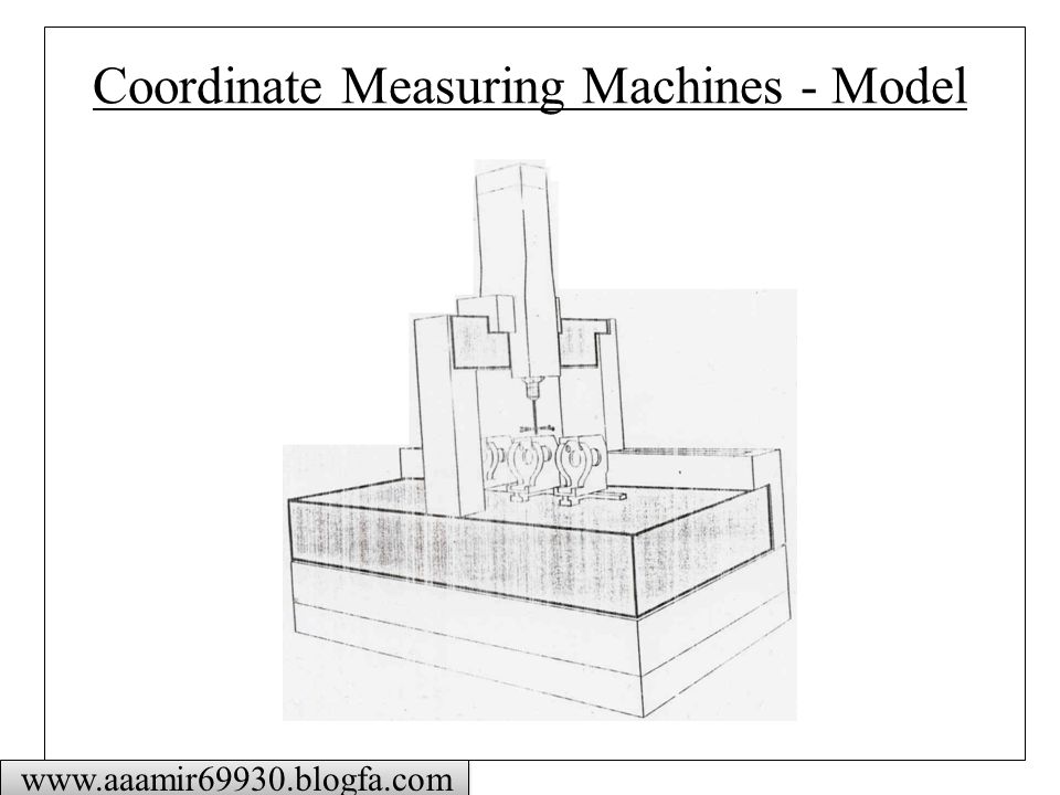
Coordinate Measuring Machines - Model
3
Types of CMM www.aaamir69930.blogfa.com
Fixed Table Cantilever Coordinate Measuring Machine Moving Bridge Coordinate Measuring Machine

4
Types of CMM www.aaamir69930.blogfa.com
Fixed Bridge Coordinate Measuring Machine Column Coordinate Measuring Machine

5
Types of CMM www.aaamir69930.blogfa.com
Moving Ram Horizontal Arm Coordinate Measuring Machine Moving Table Horizontal Arm Coordinate Measuring Machine

6
Types of CMM www.aaamir69930.blogfa.com
Gantry Coordinate Measuring Machine L-shaped Bridge Coordinate Measuring Machine

7
Types of CMM www.aaamir69930.blogfa.com
Fixed Table Horizontal Arm Coordinate Measuring Machine Moving Table Cantilever Arm Coordinate Measuring Machine

8
Probe Systems www.aaamir69930.blogfa.com Kinematic touch trigger probe
Switching probe system Continuous measuring probe system

9
Proximity Sensor y x A x = 0.5 y tan(A) www.aaamir69930.blogfa.com
sensing array x y A x = 0.5 y tan(A)
")
10
Diffracto Non-contact Laser Probe
SURFACE Measuring Range Laser Light Source Digital Solid-state sensor Lens 30o

11
Automatic Axis Alignment
Xw, Yw, Zw – Work piece related coordinate system XM, YM, ZM – Machine related coordinate system

12
Measurement with a CMM Step 1: Calibration of the stylus or probe tip with respect to the probe head reference point using a calibrated ball. Step 2: Metrological determination of the work piece position in the measuring machine-related coordinated system. Step 3: Measurement of the surface points on the work piece in the measuring machine-related coordinate system. Step 4: Evaluation of the geometric parameters of the work piece Step 5: Representation of the measurement results after coordinate transformation into the work piece related coordinate system.

13
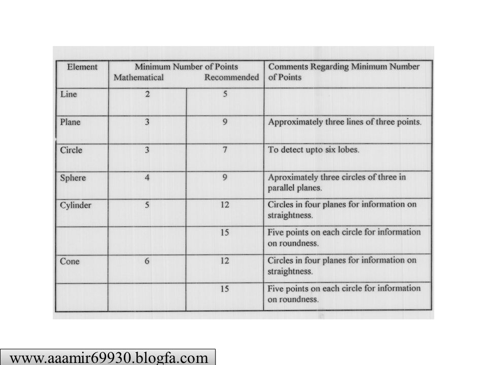
Basic Geometric elements
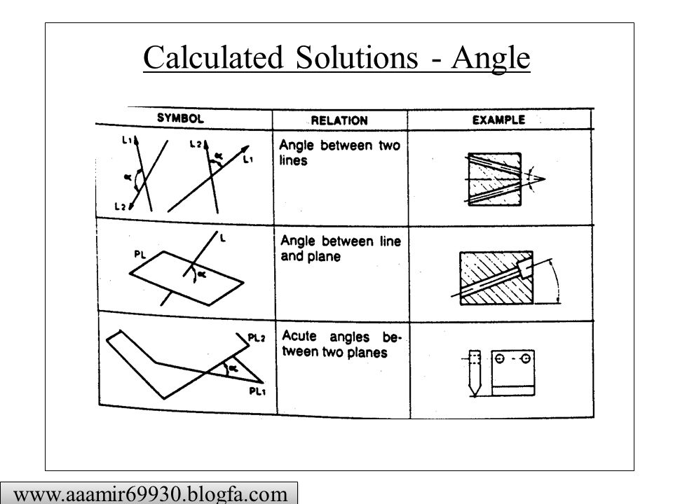
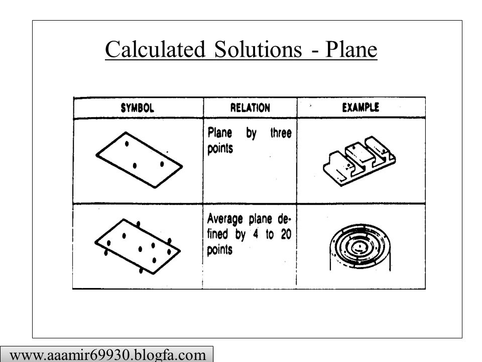
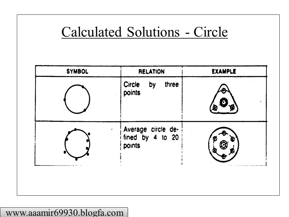
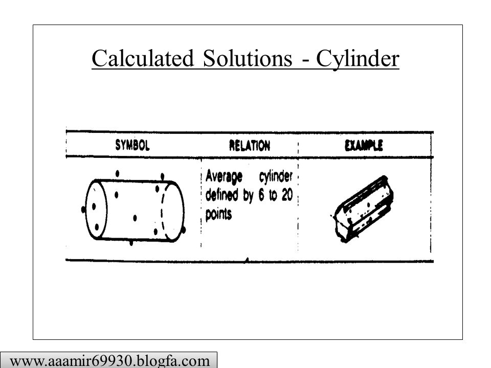
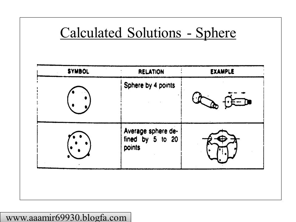
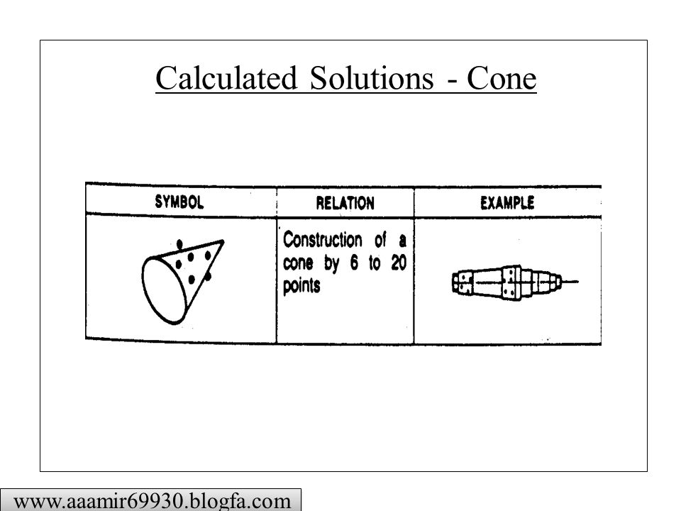
Circle: Requires 3 points for measurement: By measuring 4 (up to 50) or more points form deviation is determined Plane: Planar measurements require 4 or more points for form. The intersection of Planes 2 and 3 generate Line 5; Point 6 is the intersection of Plane 4 and Line 5 Cylinder: To define a cylinder, 5 points are necessary. Calculations provide its axis and diameter. The intersection of the Cylinder 7 and Plane 4 is Line 8. Cone: The cone (or taper) requires at least 6 points for definition. Calculations determine the cone’s included angle and its axis in space. Sphere: The location of a sphere is found by measuring 4 points is also calculated.
 or more points form deviation is determined. Plane: Planar measurements require 4 or more points for form. The intersection of Planes 2 and 3 generate Line 5; Point 6 is the intersection of Plane 4 and Line 5. Cylinder: To define a cylinder, 5 points are necessary. Calculations provide its axis and diameter. The intersection of the Cylinder 7 and Plane 4 is Line 8. Cone: The cone (or taper) requires at least 6 points for definition. Calculations determine the cone’s included angle and its axis in space. Sphere: The location of a sphere is found by measuring 4 points is also calculated.")
14
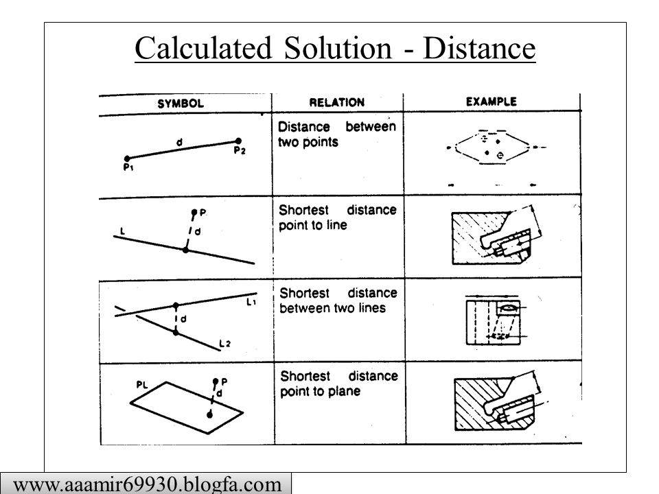
Calculated Solution - Distance
15
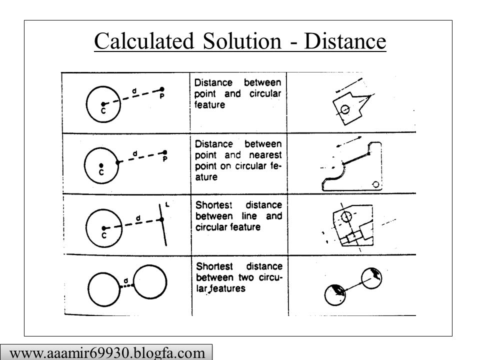
Calculated Solution - Distance
16
Calculated Solutions - Angle
17
Calculated Solutions - Plane
18
Calculated Solutions - Circle
19
Calculated Solutions - Cylinder
20
Calculated Solutions - Sphere
21
Calculated Solutions - Cone
22
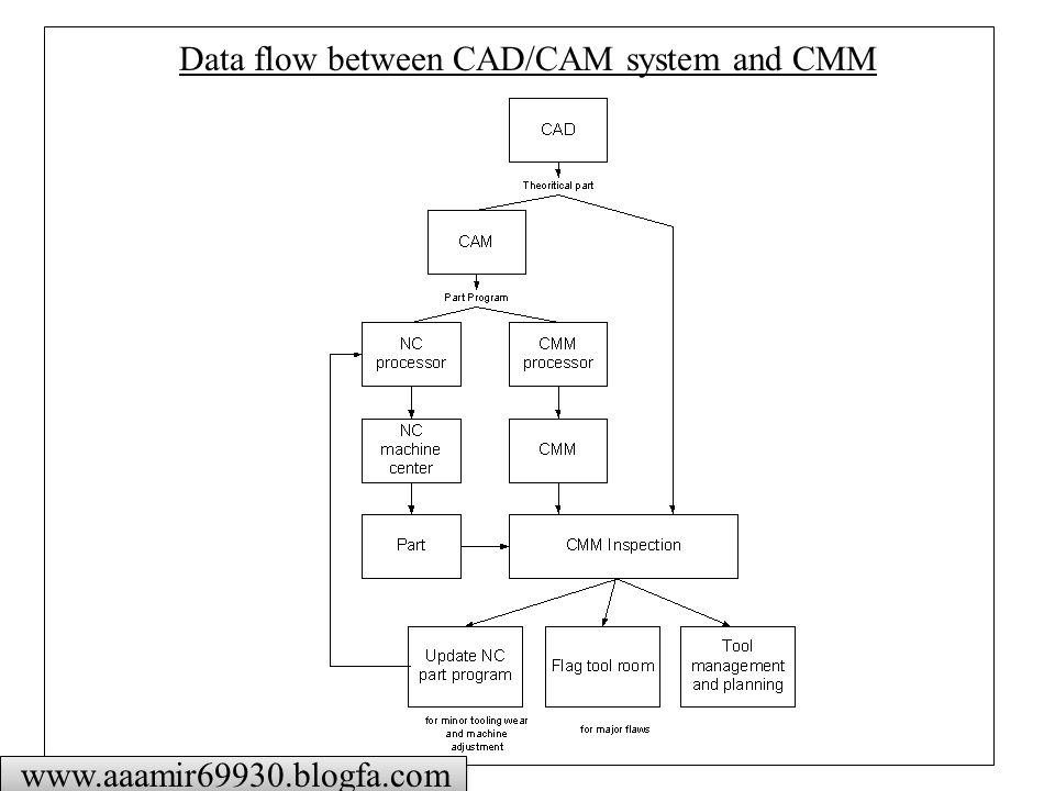
Data flow between CAD/CAM system and CMM
23
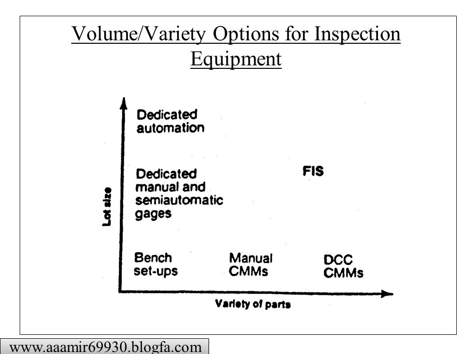
Volume/Variety Options for Inspection Equipment
24
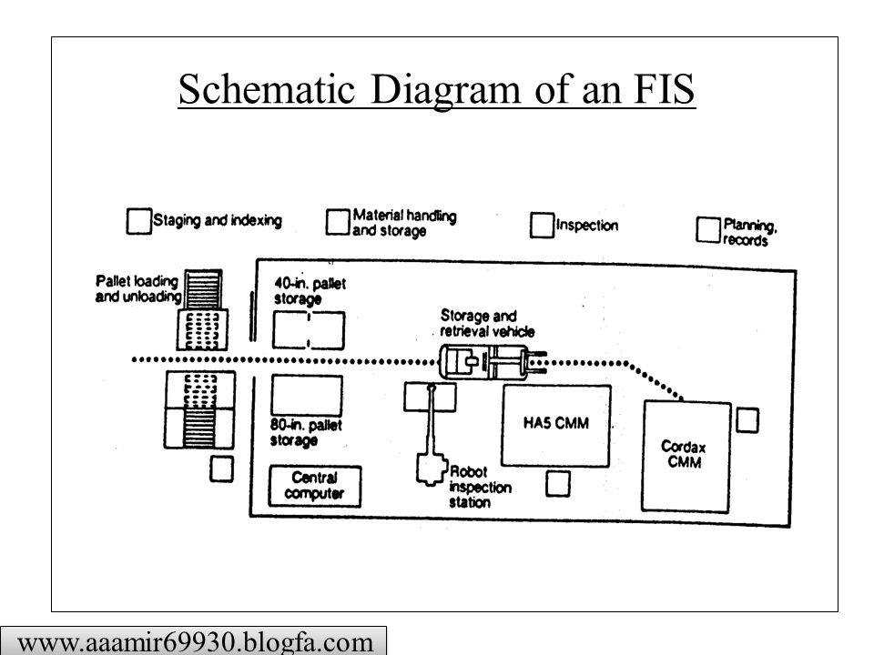
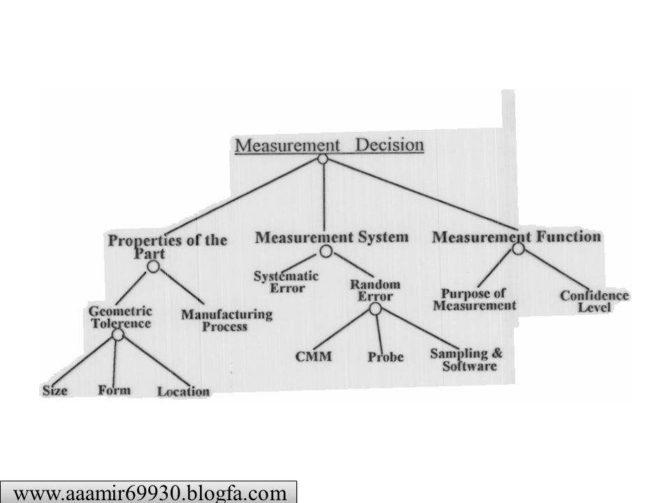
Schematic Diagram of an FIS
25
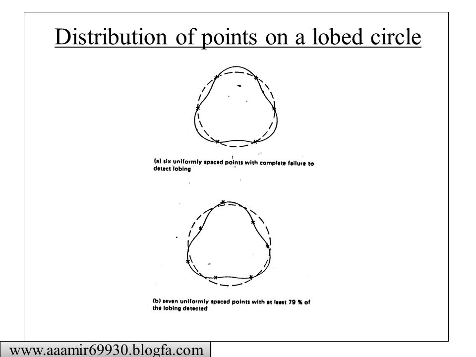
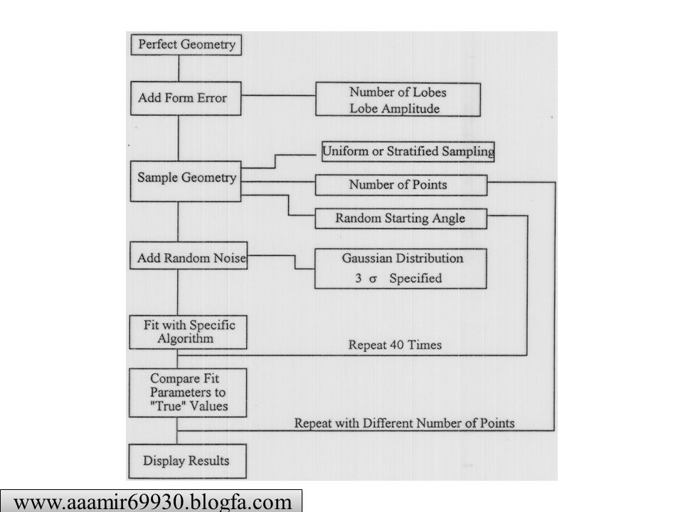
Distribution of points on a lobed circle
26
Example of insufficient sampling
Insufficient sampling of a high-frequency component results in a low-frequency alias

30
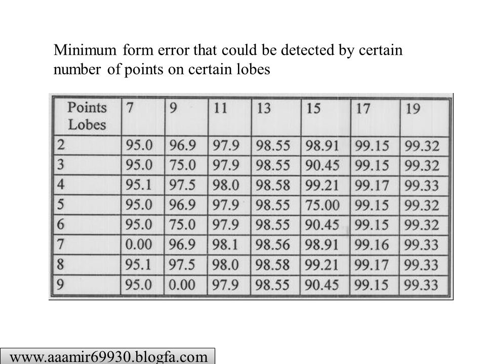
Minimum form error that could be detected by certain number of points on certain lobes
31
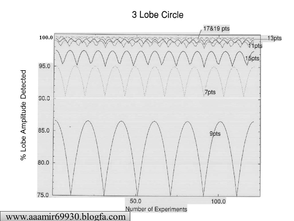
% Lobe Amplitude Detected
100.0
Similar presentations


>")


>")


. NFS Engineering Research Center for Reconfigurable Manufacturing Systems College of engineering, University of.>")


