Download presentation
Presentation is loading. Please wait.

1
WIMA DC-LINK Capacitors

2
Outline DC-Link Capacitors: Introduction Capacitor Technologies
Characteristics WIMA DC-LINK Range Applications Conclusion 2

3
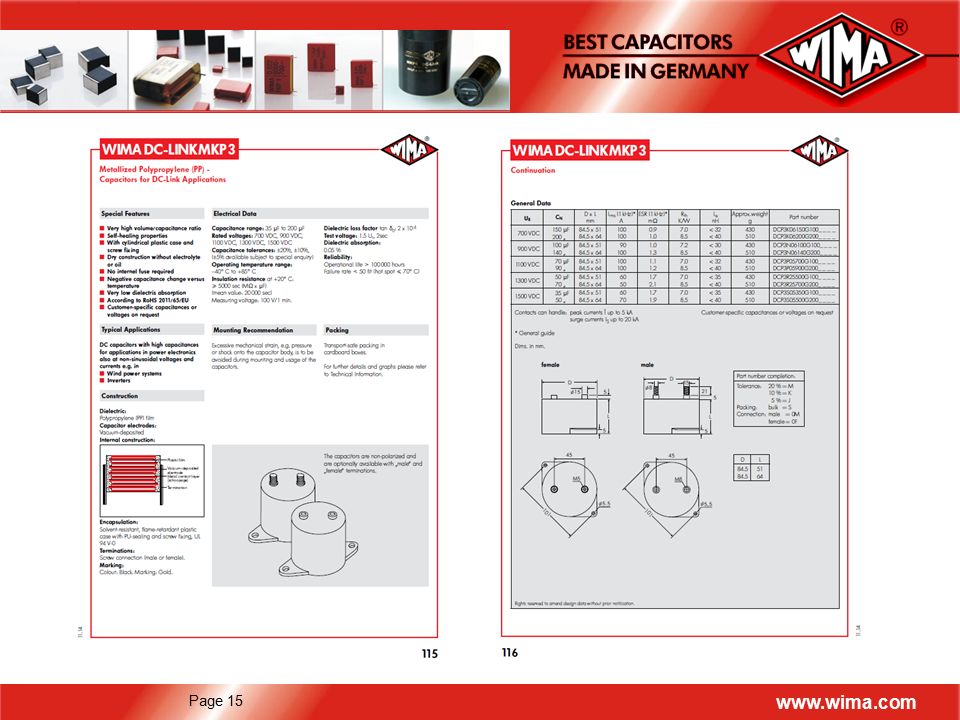
Basic Description WIMA DC-LINK capacitors are…
… designed for applications in high power converter technology … substituting more and more electrolytic capacitors … manufactured with low loss Polypropylene dielectric … showing high current capability and low dissipation/self-heating … available in rectangular and cylindrical cases with capacitances up to µF … available in various customized versions

4
Comparison of DC-Link Capacitor Technologies: Film Cap vs
Comparison of DC-Link Capacitor Technologies: Film Cap vs. Electrolytics Technical characteristics Technology Capacitance per Volume ESR Irms Stability / Reliability Plastic Film Improving Low High Electrolytic Medium Capacitance drift with temperature 115% 105% 95% Plastic Film Electrolytic 85% 75% -60 -35 -10 15 40 65 90

5
WIMA DC-Link Characteristics
Very high volume / capacitance ratio High voltage rating per component Very low dissipation factor (ESR) Very high insulation resistance Excellent self-healing properties Long life expectancy Non-polar construction Particularly reliable contact configuration High shock and vibration resistance Outstanding mechanical stability Solvent-resistant, flame retardant plastic case (in accordance with UL 94 V-0)
 Very high insulation resistance. Excellent self-healing properties. Long life expectancy. Non-polar construction. Particularly reliable contact configuration. High shock and vibration resistance. Outstanding mechanical stability. Solvent-resistant, flame retardant plastic case (in accordance with UL 94 V-0)")
6
Requirements and Technical Solutions
Basic Criteria Technical Solutions High ripple current capability Low ESR & ESL Wound film technology PP film material Variable terminal configurations High self-healing capability Thermal / electrical stability Reliability Metallized plastic film High resistance to mechanical stress Plastic case (UL 94 V-0) Terminal robustness (according to capacitor size)
 Terminal robustness (according to capacitor size)")
7
Self-healing Characteristics of Metallized Film
During operation voltage spikes and/or high temperature may impact the capacitor An electrical breakdown occurs causing temperatures of several thousand °C The metallization evaporates in the area of the break-down channel A metal-free zone is created isolating the area electrically. The capacitor has regenerated (self-healed) completely. b = breakdown channel c = current flow d = de-metallized area Schematic depiction of the self-healing process Isolated area after the self-healing process
 completely. b = breakdown channel c = current flow d = de-metallized area. Schematic depiction of the self-healing process. Isolated area after the self-healing process.")
8
Terminal Configurations
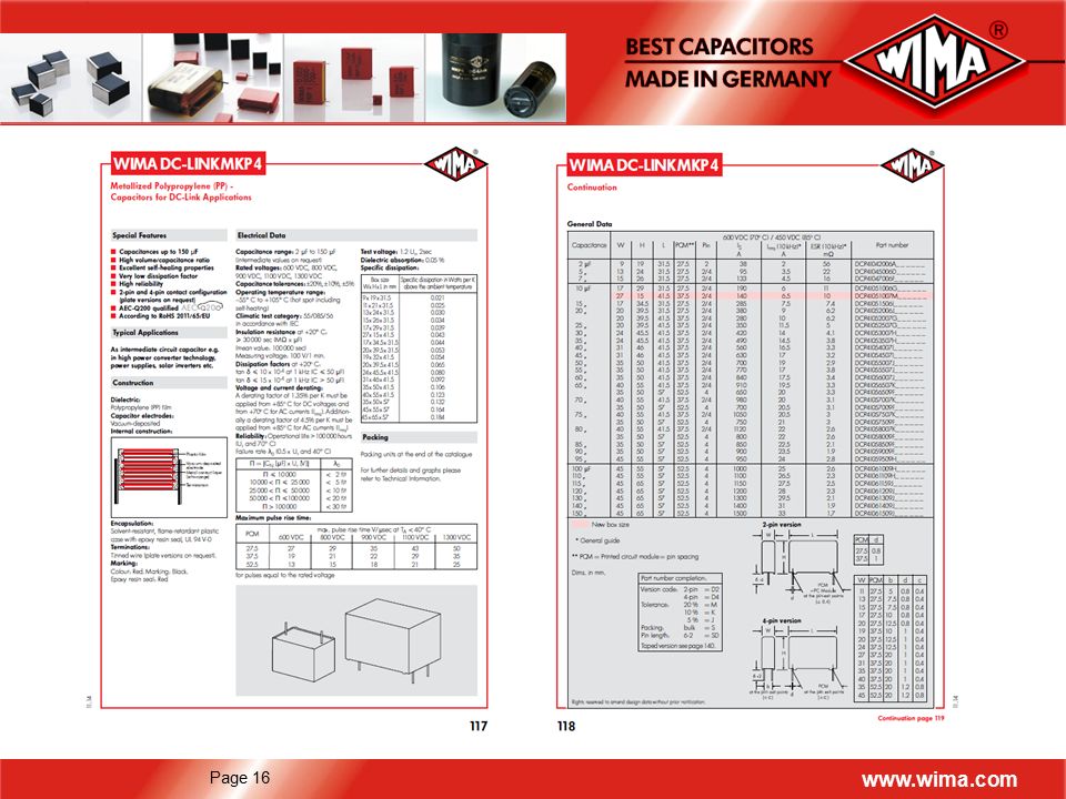
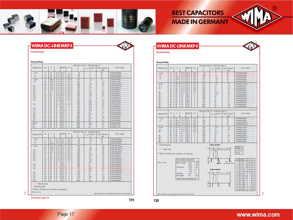
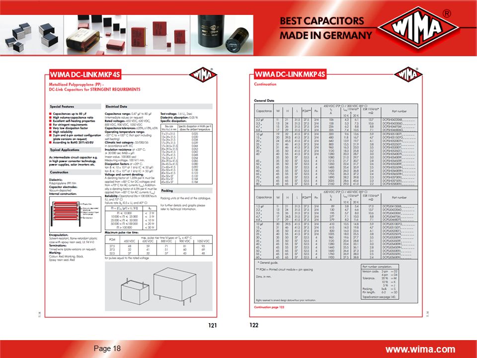
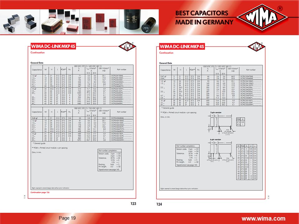
DC-Link Termination Options: Cylindrical plastic case with screw fixing and male or female connections DC-LINK MKP 3 2-pin and 4-pin versions (screwable plate versions on request) DC-LINK MKP 4 / DC-LINK MKP 4S Cylindrical capacitor body with pin connections for PCB mounting DC-LINK MKP 5 Cylindrical capacitor body with male or female connections for bus bar mounting DC-LINK MKP 6 Versatile and safe contact configurations by screwable plates DC-LINK HC / DC-LINK HY
 DC-LINK MKP 4 / DC-LINK MKP 4S. Cylindrical capacitor body with pin connections for PCB mounting. DC-LINK MKP 5. Cylindrical capacitor body with male or female connections for bus bar mounting. DC-LINK MKP 6. Versatile and safe contact configurations by screwable plates. DC-LINK HC / DC-LINK HY.")
9
Terminal Configurations
DC-LINK MKP 3: Cylindrical capacitor body with screw fixing for PCB mounting Capacitors are non- polarized and are designed with male or female screw connection. DC-LINK MKP 4 / DC-LINK MKP 4S: 2-pin or 4-pin version (screwable metal plate versions on request) Capacitors are non- polarized W PCM b d c 11 13 15 17 20 1719 24 27 31 35 40 45 27.5 37.5 52.5 5 7.5 10 12.5 20 20 0.8 1 1 1 1.2 0.4 D L 84.5 51 64 PCM d 27.5 37.5 0.8 1
 Capacitors are non- polarized. W. PCM. b. d. c D. L PCM. d")
10
Terminal Configurations
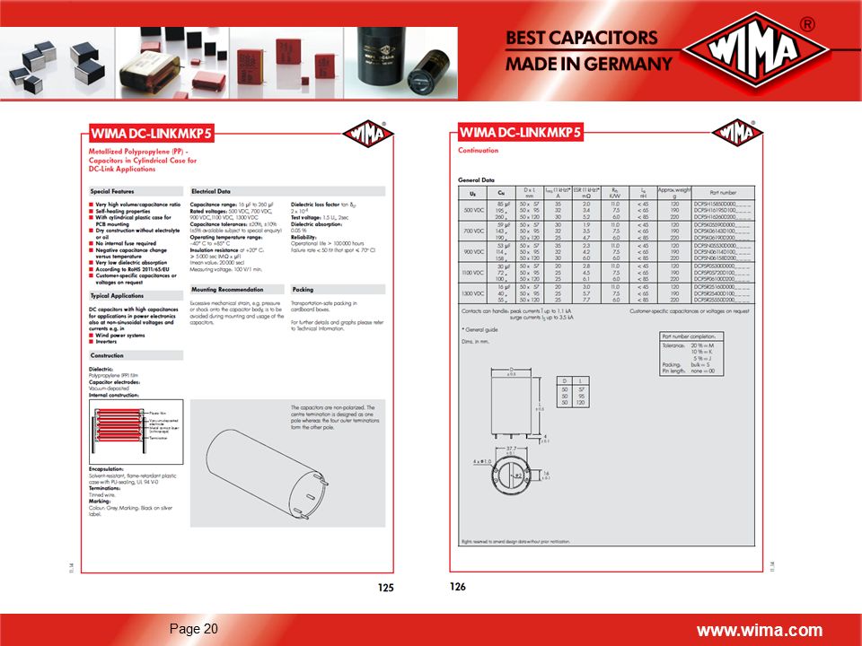
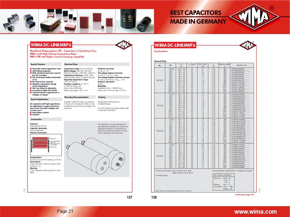
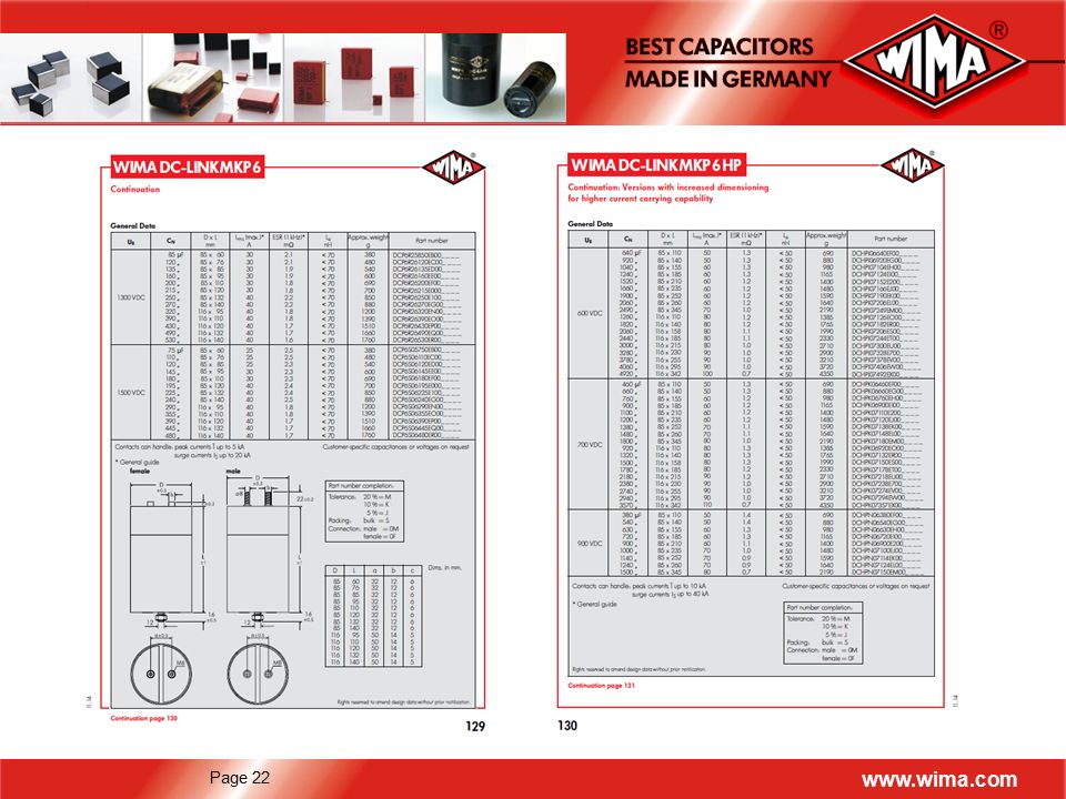
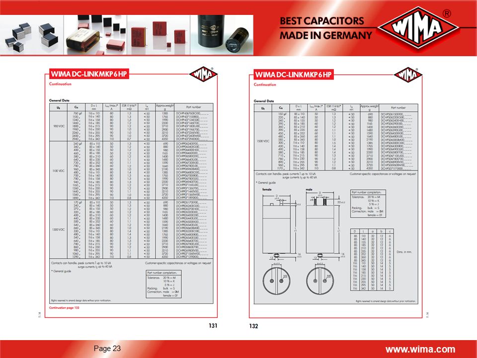
DC-LINK MKP 5: Cylindrical capacitor body with pin connections for PCB mounting Capacitors are non-polarized. The centre termination is designed as one pole whereas the four outer terminations form the other pole. DC-LINK MKP 6: Cylindrical capacitor body with screw connec-tions for bus bar mounting Capacitors are non-polarized and are designed with male or female screw connection. D L a b c 85 116 110 140 155 185 210 235 252 260 345 158 215 230 255 295 342 32 50 12 14 6 5 D L 50 57 95 120 D L a b c 85 116 60 76 95 110 120 132 140 32 50 12 14 6 5

11
Terminal Configurations
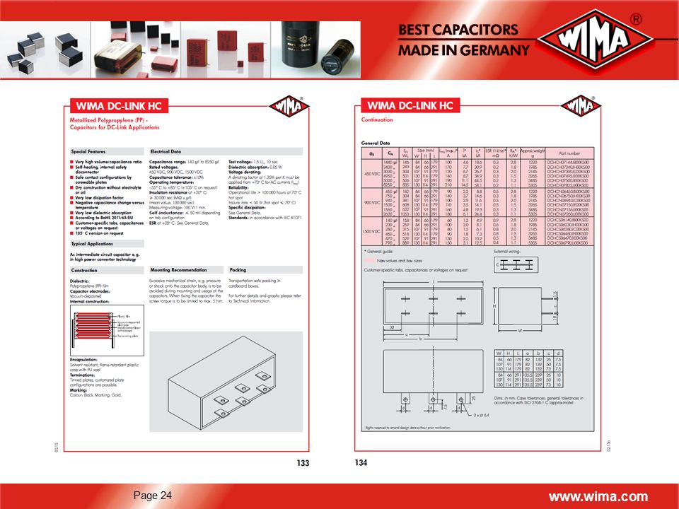
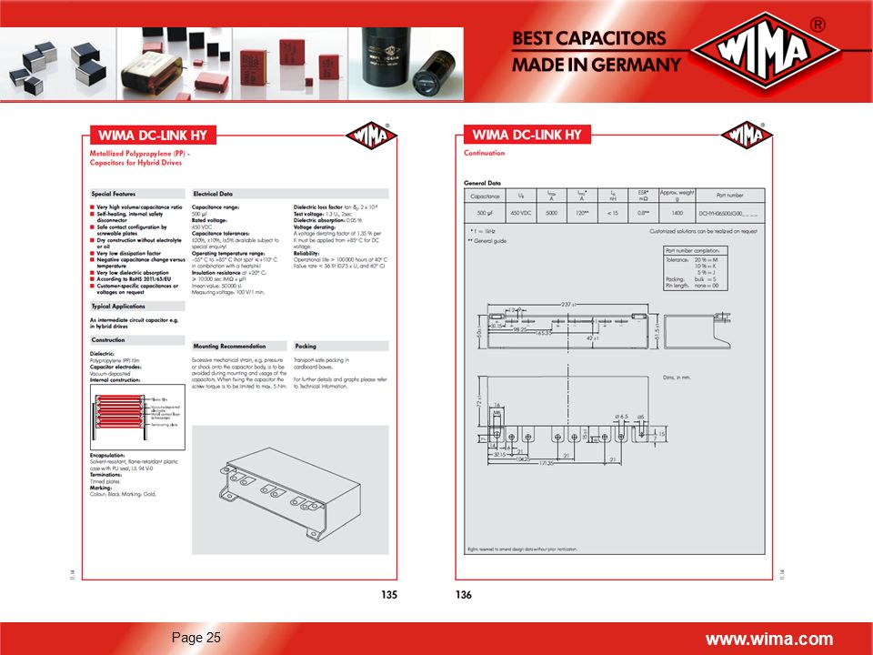
DC-LINK HY: Rectangular capacitor body with screw fixing and screwable plate connections Customized capacitors with variable contact configurations on request. DC-LINK HC: In rectangular plastic case with PU sealing Capacitors are non-polarized. Customer-specific tabs, capacitances or voltages on request. W H L a b c d 84 107 130 66 91 114 135.5

12
Speed Adjustment and Control of Three-Phase AC Motors
Application: Frequency Converter Speed Adjustment and Control of Three-Phase AC Motors Mains Mains Filter Mains Rectifier Voltage Motor Inverter Motor Intermediate Circuit Frequency Converters are designed for starting, braking, speed adjustment as well as control or positioning of three-phase AC motors. Fields of application: Trains, Freight Elevators, Wind Power Plants

13
Application: DC/DC Converters
Layout of a DC distribution network for offshore windparks DC/DC converter

14
DC capacitor as intermediate circuit buffer
Typical Converter Circuit using a DC-Link Capacitor Requirements for DC-LINK For plastic film capacitors highest volume/capacitance ratio combined with high DC voltage strength by self-healing capability Intermediate circuit voltage =/> 450 V High ripple current capability and resistance against superimposed AC- and pulse voltage respectively Mains Rectifier Buffer Motor Inverter Mains Motor DC capacitor as intermediate circuit buffer

26
Customized Solutions 2 x µF 800 VDC 1100 µF 600 VDC

27
Customized Solutions 500 µF 450 VDC 350 µF 800 VDC

28
Selection of Capacitors for Customized Applications
Operational Data Required: Electrical data of the capacitor - Capacitance - Rated voltage (DC / AC) - Tolerance* - Dimensions* / PCM* Electrical data of the application - Voltage Current - Pulse frequency / Repetition frequency - Time axis - Pulse rise time* Application data - Ambient temperature - Kind of application* Oscillogram (voltage and current) appreciated *optional
 - Tolerance* - Dimensions* / PCM* Electrical data of the application - Voltage - Current - Pulse frequency / Repetition frequency - Time axis - Pulse rise time* Application data - Ambient temperature - Kind of application* Oscillogram (voltage and current) appreciated *optional.")
29
Conclusion WIMA film capacitor technology is
replacing more and more electrolytic capacitors in DC-Link applications made possible due to: Longer life time and growing efficiency requirements in applications Parameter stability that makes the design easier New film cap designs with greater density of capacitance per volume (reducing the size) For more information:
 For more information:")
30
Cross-Reference List Competitors 30 Kemet Vishay TDK/Epcos AVX
Electronicon Faratronic Product Family Range Description Picture DC-LINK MKP 3 35 µF – 200 µF 700 VDC to 1500 VDC C4DE B2563… FFVE/FFVI (FFVS) E53 C3A C3A(G) DC-LINK MKP 4 DC-LINK MKP 4S 2 µF – 150 µF 450 VDC to 1300 VDC C4AE MKP1848 MKP1848C MKP1848S B32674…678 B32774…778 FB FE C3D DC-LINK MKP 5 16 µF – 260 µF 500 VDC to 1300 VDC E61 DC-LINK MKP 6 75 µF – 4920 µF 600 VDC to 1500 VDC C44U ESTA: HDMKP B2562… FFLI PK16 XC (E50) C3B DC-LINK HC 140 µF – 8250 µF 450 VDC to 1500 VDC Customized solutions on request PCC LP: B25655… FFLC C36 DC-LINK HY 500 µF 450 VDC B25655 C3N C36 30
 E53. C3A C3A(G) DC-LINK MKP 4 DC-LINK MKP 4S. 2 µF – 150 µF 450 VDC to 1300 VDC. C4AE. MKP1848 MKP1848C. MKP1848S. B32674…678. B32774…778. FB FE. C3D. DC-LINK MKP µF – 260 µF 500 VDC to 1300 VDC. E61. DC-LINK MKP µF – 4920 µF 600 VDC to 1500 VDC. C44U. ESTA: HDMKP. B2562… FFLI. PK16 XC (E50) C3B. DC-LINK HC. 140 µF – 8250 µF 450 VDC to 1500 VDC. Customized solutions on request. PCC LP: B25655… FFLC. C36. DC-LINK HY. 500 µF 450 VDC. B C3N C")
31
Thank You ! WIMA Spezialvertrieb elektronischer
Bauelemente GmbH & Co.KG Besselstr. 2-4 D Mannheim Germany Phone: Fax: Internet:

Similar presentations


Capacitor.>")


